Article|TSD-11A
Your Warehouse Floor Is Not a Runway
Why a 1973 airport design method ended up sizing forklift floors, what it gets right, and why accepting the same inputs is not the same as solving the same problem.
The Slab Designer, LLC | Published November 3, 2026 | Revised November 4, 2026
How do you design a floor for a 100,000 lb container handler?
If you have been in this business a while, there is a decent chance the answer was "run it through AirPave." Or, if you have been in it even longer, "the PCA airport program." I'll own my part here: I wrote the AirPave user's manual when I was at ACPA, and the manual cheerfully walks through a dump truck as an example of a non-aircraft load. Flexible inputs were a selling point.
They still are. But I've spent the last few years re-reading the original references, and I think it is worth asking a question the manual didn't: just because a method accepts your inputs, does it fit your problem?
Two bulletins, one author
The airport method is older than most people realize. PCA first published Design of Concrete Airport Pavement in 1950 and revised it just five years later. The 1955 edition sized slabs by laying tire outlines over Pickett and Ray's influence charts and counting blocks, and it already promised to handle "any number of tires with any arrangement and with any tire pressure or contact area."
In the 1970s, Robert Packard at the Portland Cement Association wrote two design methods that a lot of the concrete world still recognizes. One was Design of Concrete Airport Pavement (EB050, 1973). The other was the industrial floor charts (1976), which grew into PCA's Concrete Floors on Ground (EB075).
Both rest on the same idea: Westergaard's stress for a load in the middle of a big slab sitting on a uniform bed of springs. The floor charts cover a few fixed cases, such as a single or dual lift truck axle, rack posts, and distributed storage. The airport method came with a computer program, PDILB, that would take any wheel layout, any tire size, and any tire pressure, find the worst spot to park the gear, and give you the stress. That flexibility is why engineers with straddle carriers, top-picks, and transporters went to the airport method. Nothing else would take their inputs.
We rebuilt it, and it checks out
At The Slab Designer, we rebuilt the airport method from the original equations in a free tool, PCA Airport Thickness Design, at slabs.design/pca-airport. (Its sibling, PCA Slab Thickness Design at slabs.design/pca, does the same for the 2008 floor charts.)
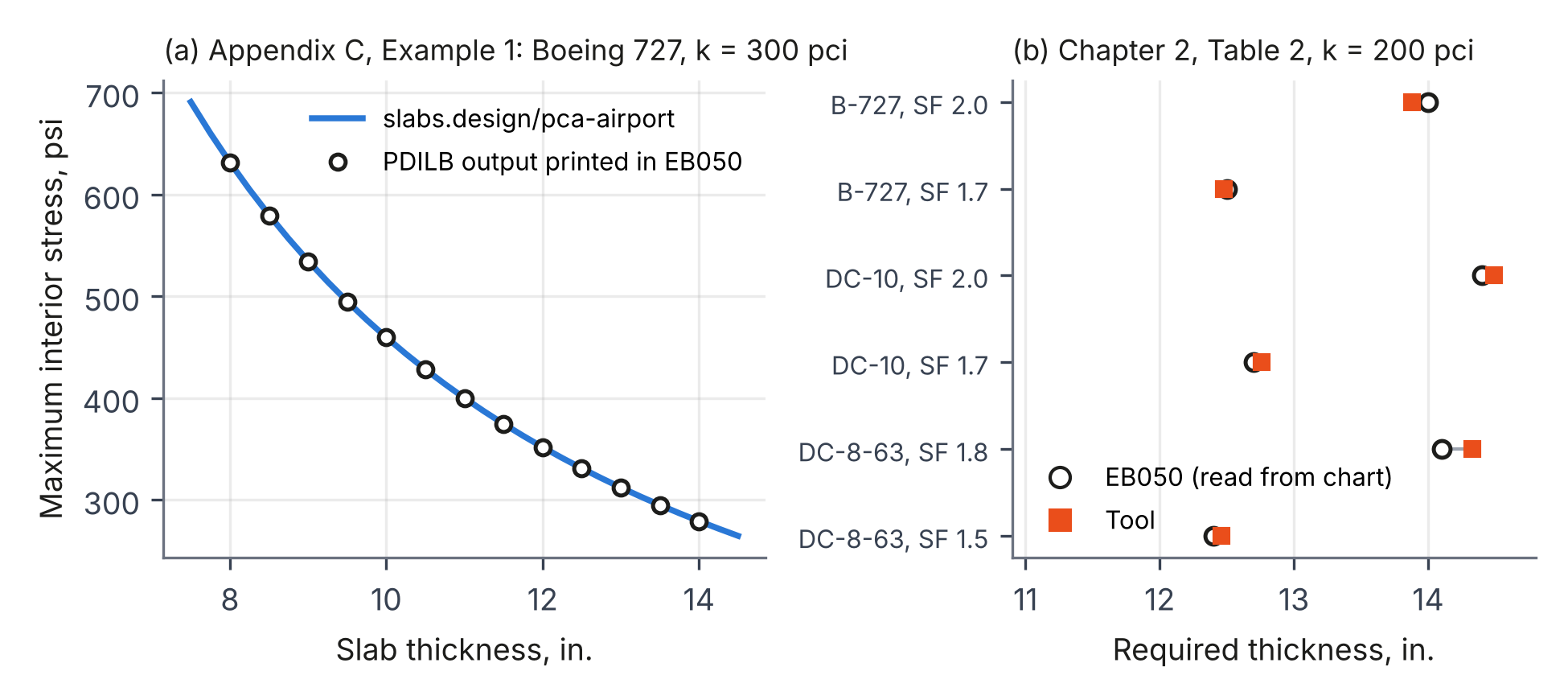
The fun part about the 1973 bulletin is that Packard printed his actual computer output. So we could check our work against his, number for number (Figure 1). For his Boeing 727 example, our stresses land within 0.13% of all thirteen he printed. For his DC-8 example, they match to the fourth decimal once we split each tire into exactly 20 slices, the way his 1967 program did. We even found a spot where his program appears to have stopped searching too early: for the C-5A at one stiffness, the true worst-case stress is 3.8% higher than the printout, near a different wheel. For the 2008 floor method, the tool reproduces PCA's printed examples too, like the 235 mm (9.25 in.) free-edge thickness in its metric lift truck problem.
So the math is what PCA said it was. The question is whether it is the right math for a warehouse.
Same inputs, different problem
A design method is more than a stress formula. It is a stress formula plus a limit you design against, and that limit was calibrated to the way a particular kind of pavement fails. Move the formula to a different kind of pavement and the limit doesn't come with it.
Airfields and warehouse floors fail differently.
- Airfields. Airfield slabs tend to be thick, in my experience thicker than flexure alone would require, often because owners want bigger panels and fewer feet of joint, since joints were seen as the problem. The headaches on an airfield are mostly foreign object debris (a chunk of concrete in a jet engine is a very bad day) and durability, because the pavement lives outdoors. And every wheel is a big, soft, pneumatic aircraft tire.
- Warehouses. Floors live indoors, dry from the top, and curl at their joints. Lift trucks and order pickers roll on small, hard wheels. A hard wheel hitting the edge of a joint that deflects under it chips the edge, over and over, until you have a spalled joint. Airfields carrying only pneumatic tires just don't see that mechanism.
Even the wheel itself is described differently. The airport method models every wheel as a tire, an oval contact patch sized from the load and the tire pressure. A small, hard lift truck wheel doesn't make an oval. It touches the floor in a narrow strip across its width, closer to a short line load than a tire footprint. You can type a hard wheel into the program, but what it analyzes is still a tire.
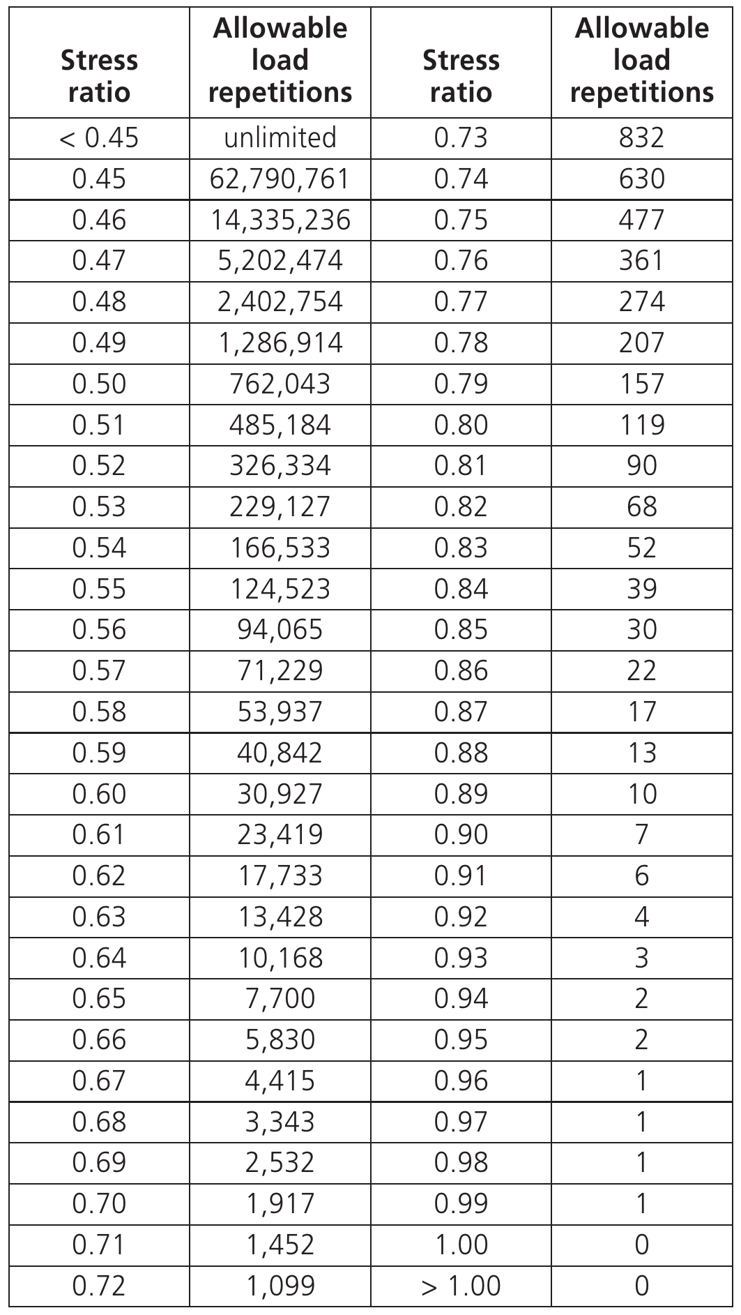
That is why the floor guidance designs against different limits. ACI 360R-10 suggests keeping the differential deflection across a joint to about 0.010 in. for small, hard wheels and 0.020 in. for larger, cushioned wheels. It ties thickness to a fatigue curve between stress ratio and load repetitions. The airport method has no joint deflection limit at all, and its fatigue table says a stress ratio of 0.50 can be repeated forever. PCA's 2008 floor table puts the same stress ratio at about 760,000 repetitions, which a busy cross-aisle can use up.
The middle of the slab is the easy part
Even PCA agrees that an interior load doesn't describe a floor with joints. In 2001, PCA added a "joint factor" of up to 1.6 to its floor method, because finite element analysis showed stresses at joints 50% to 60% higher than in the middle of a panel. In 2008, it added free-edge charts. AirPave did something similar for the airport method with a joint factor and a free-edge factor, built from a handful of finite element runs with a fixed 25% load transfer assumed at interior joints.
Here's the funny part: the airport method knew this all along. The 1955 edition says plainly that its charts are "theoretically correct when a load is located in the interior of a slab." It skipped the edge charts for two reasons: free outside edges aren't critical on an airfield, and "adequate load transfer is provided at all interior joints."
The first reason is fair, once you read it right. Airfield edges and joints are still critical; cracks can start there the same as in a floor. What the bulletin means is that an airfield has no free edges in traffic. Airplanes don't drive off the side of the runway, so every joint a wheel crosses is an interior joint.
The second reason deserves a closer look. Lots of airfield joints aren't doweled. A common practice is to dowel or tie the longitudinal joints and leave the transverse joints undoweled. Panels are big, because fewer joints was the goal, and bigger panels need thicker slabs. And airfields very often sit on stabilized bases, sometimes lean concrete, then a stone layer, then the concrete pavement. That support controls deflection across the whole system, and it shows up as load transfer when you measure the joints. So the load transfer was real, but a lot of it came from the support under the joint, not the joint itself. Airfield design practice treated the free edge as the critical case, and since airfields didn't have any, interior joints, doweled or not, were treated as good enough.
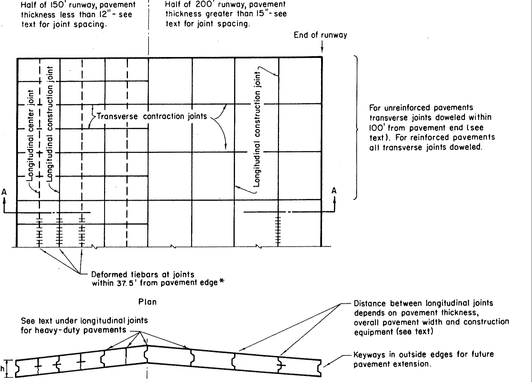
Where a joint couldn't share load, both the 1955 and 1973 editions made the edges about 20% thicker. Stress goes roughly with the square of thickness, so that's 1.2 x 1.2 = 1.44, right in the range of the floor method's later joint factor. When an engineer borrows a PDILB or AirPave stress for a warehouse, the stress comes along and that thickened-edge requirement can stay on the runway.
Here is what the joint alone does to one vehicle from AirPave's list, a dual-wheel container handler with 17,270 lb tires, on a fair subgrade (k = 150 pci [41 MPa/m]), 650 psi concrete, and a safety factor of 2 (Figure 4). At the slab interior: 9.5 in. At an interior joint, with AirPave's joint factor: 11.5 in. At a free edge: 14.0 in. That's 4.5 in. of concrete from where the load sits relative to the joints alone.
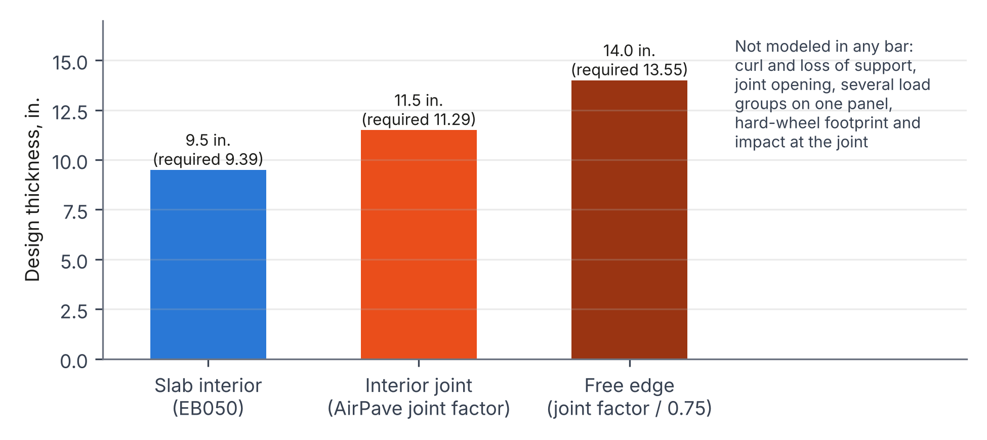
And that is before curl. ACI 360R-10 reports curling stresses of 200 to 450 psi, the same order as the stress we let the wheels put in. It's tempting to just add the two, and I've seen it done plenty. It doesn't work that way. A curled slab isn't sitting on the ground at its joints. When a wheel rolls up to the joint, it pushes the slab back down, so the support changes with the load, and the stress changes with the support. The real answer can be higher or lower than the sum, and the worst tension can move to the top of the slab. You have to model the two together.
A high factor of safety, of unknown size
Here's the thing: lots of floors designed with the airport method have done just fine. I'm not saying the sky fell.
What I am saying is that we don't know why they did fine, at least not in numbers. A safety factor of 2 on an interior stress covers a lot, and it has been quietly absorbing everything the method leaves out. Do the arithmetic for a free edge, load only. A slab with a safety factor of 2.0 in the middle of the panel has about 2.0 / 1.77 = 1.13 at a free edge, using AirPave's free-edge factor. Then there's curl, which, as above, you can't just add on.
There's another half to this, and it's on the capacity side. The 650 psi we design against comes from breaking a small beam on two supports. A slab-on-ground isn't a beam. It's supported over its whole area, it can shift load around, and it carries more than the beam test says. If you computed honest stresses at a curled joint and compared them with beam strength, you'd predict cracked floors in a lot of buildings that are doing fine. That's why SLABS converts beam strength to slab capacity. Getting both the demand and the capacity right is the only way I've found for the equations to even begin to explain how slabs-on-ground have actually performed.
So the honest description is this: the airport method has served the industrial space well for decades, with a high factor of safety whose actual value I haven't found anyone calculating. That is not a reason to use it to justify a thinner slab. And it is not evidence that a floor designed this way was designed for its joints.
Stepping stones, then a long pause
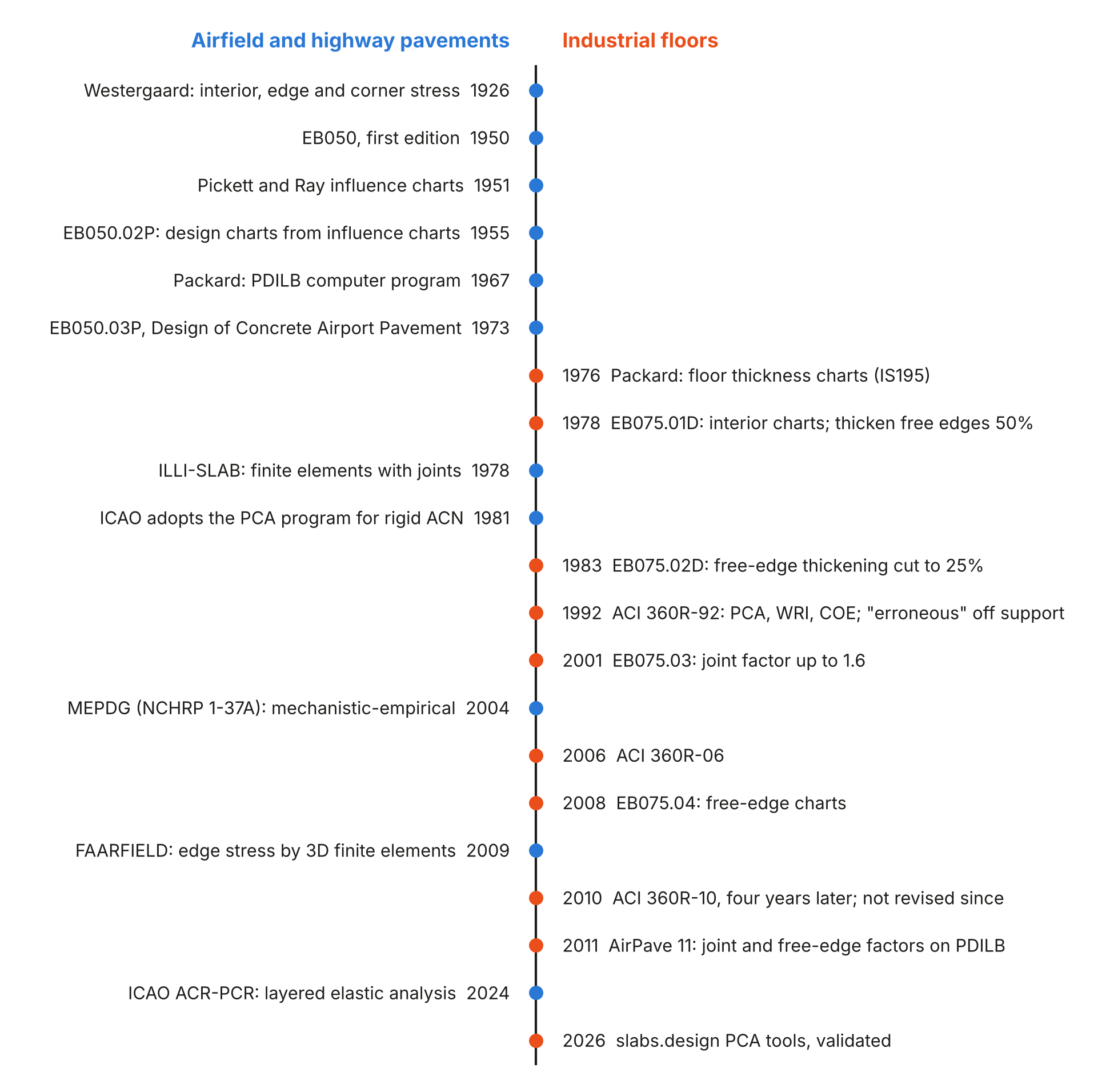
Both PCA bulletins were meant to be stepping stones, and the 1955 edition says so. It explains that a better subgrade model was still being worked on, and that "it is believed a practical solution soon will be found. Until the application of the elastic solid theory is developed, the method herein presented may be used with assurance that it will give safe results." Safe for its time and its conditions, pending something better. By 1973, on its third edition in 23 years, the airport method had a computer program, a fatigue analysis, and higher safety factors for runways. The floor method went from the 1976 charts, to a 1978 bulletin that said to thicken the slab 50% where lift trucks cross a free edge (25% by 1983), to joint factors in 2001 and free-edge charts in 2008. Each edition fixed something the last one missed. That's how engineering guides are supposed to work.
Then the consensus guidance for floors stopped moving (Figure 5). Floor design itself didn't stop. The innovation moved outside the committees: proprietary flooring systems, admixtures, dowel and fiber design software, and tools like ours. Finite element programs that model joints have been around since the late 1970s. Highways went mechanistic-empirical in 2004. The FAA moved airfield design to 3D finite element edge stresses in 2009, and the international airport rating system retired the PCA program in 2024. The airport community has moved on from the airport method. The floor community is still borrowing it. ACI 360's first guide, in 1992, already said its three thickness methods "give erroneous results" wherever a slab isn't touching the ground, and that microcomputers might make finite element analysis practical "in the future." The guide was revised in 2006, again in 2010, four years later, with the same three methods and the same sentence, and not since.
That's the odd part to me. PCA spotted the gaps in its airport method and fixed them five years after it first came out. ACI turned its floor guide around in four. We're good at seeing the flaws in a first version of something. Once a method settles into specs, software, and the standard of care, we get a lot slower about fixing it, and a long record of floors that did fine starts to look like proof the method was right, instead of proof the factor of safety was big.
That's the gap we're working on at The Slab Designer: getting theory, guidance, and design for slabs-on-ground caught up with mechanistic-empirical modeling, with joints, load transfer, curl and load solved together, loss of support, real loads on real panels, and the capacity of a slab instead of a beam. Rebuilding the PCA methods is part of that. It makes the published methods easy to reproduce, shows their bounds, and makes it plain where they stop.
What to ask on your next project
If your floor or yard is being designed with the airport method or AirPave, these are fair questions:
- What performance criterion is the thickness designed against? A safety factor on interior stress, a fatigue curve, a joint deflection limit, or all three?
- What was assumed at the joints? Was load transfer assumed, specified, or modeled?
- Were curl and loss of support at the joints considered, and were they modeled with the load or just added to it?
- Is the stress compared with a beam strength or with the slab's capacity?
- Is the traffic on pneumatic tires, or on small, hard wheels that will hit the joint edges?
- Was the wheel modeled as a tire footprint, or as the narrow contact of a hard wheel?
If the answers are "interior stress," "assumed," "no," "a beam," "hard wheels," and "a tire," you have a floor with a high factor of safety of unknown size. That might be fine. It's OK to want to know.
Sources
ACI Committee 360, ACI 360R-92, Design of Slabs on Grade, American Concrete Institute, 1992 (reapproved 1997), and ACI 360R-06, 2006.
Portland Cement Association, Design of Concrete Airport Pavement, EB050.02P, 1955. Quotations from "Selection of Safety Factor" and the Appendix.
Packard, R. G., Design of Concrete Airport Pavement, EB050.03P, Portland Cement Association, Skokie, IL, 1973. Quotations from Chapter 2; computer output from Appendix C. https://zemubarek.wordpress.com/wp-content/uploads/2014/04/design-of-concrete-airport-pavement.pdf
Packard, R. G., Computer Program for Airport Pavement Design, SR031P, Portland Cement Association, 1967.
American Concrete Pavement Association, AirPave Airport Pavement Design Program, User's Manual, MC006P, rev. 10-2011.
Packard, R. G., Slab Thickness Design for Industrial Concrete Floors on Grade, IS195.01D, Portland Cement Association, 1976.
Spears, R. E., Concrete Floors on Ground, EB075.01D, Portland Cement Association, 1978.
Spears, R. E., and Panarese, W. C., Concrete Floors on Ground, EB075.02D, second edition, Portland Cement Association, Skokie, IL, 1983.
Farny, J. A., and Tarr, S. M., Concrete Floors on Ground, EB075, fourth edition, Portland Cement Association, 2008.
American Concrete Institute Committee 360, ACI 360R-10, Guide to Design of Slabs-on-Ground, Farmington Hills, MI, 2010.
Covarrubias, J. P., Rodden, R., Khazanovich, L., Roesler, J., and Parkes, N., "Mechanistic-Empirical Design of Concrete Slabs-on-Ground," Concrete International, July 2026.
Federal Aviation Administration, Airport Pavement Design and Evaluation, Advisory Circular 150/5320-6E, with FAARFIELD, 2009.
International Civil Aviation Organization, ACR-PCR method for aircraft and pavement rating, applicable from November 2024.
The Slab Designer, LLC, PCA Airport Thickness Design, free online tool, https://slabs.design/pca-airport, 2026.
The Slab Designer, LLC, PCA Slab Thickness Design, free online tool, https://slabs.design/pca, 2026.
Related in This Series
- Technical paper on this topic: PCA's Airport Pavement Method on Industrial Floors
Validates a rebuild of PCA's 1973 airport method and explains why its flexible inputs do not make it an industrial floor design basis.
- The Design Guide a New Engineer Can't Design From
A new engineer follows ACI 360R-10 step by step and finds the places it raises an issue and stops.
- The Floor Design Guide That Calls Its Own Results Erroneous
What owners should know about the trap built into the industry's main slab design guide.
- If You Can't Model It, You Can't Prevent It
A plain-language summary of our Concrete International and Concrete articles, and why, in our rack example, the highest stress is where the legacy methods don't look.
- The Roads Already Ran the 0.1% Experiment
Light steel through the joints has a name in highway engineering, and most DOTs stopped building it decades ago.
Revision history
- November 4, 2026: Revised the airfield joint discussion; adopted slab interior, interior joint, and free edge terms; added the wheel footprint point and PCA's 1973 jointing plan; added PCA's 2008 fatigue table; added metric units to k-values.
- November 3, 2026: First published on slabs.design/knowledge.
To cite this article, use the citation printed in the PDF. It includes the revision date, so readers can match your citation to the text you read.