Article|TSD-10A
The Roads Already Ran the 0.1% Experiment
Light steel through the joints of a jointed slab has a name in highway engineering, and most state DOTs stopped building it decades ago.
The Slab Designer, LLC | Published November 2, 2026 | Revised November 4, 2026
Here's a fun one to bring up at a pavement conference: the existence of continuously reinforced concrete pavement is evidence that a little steel didn't solve the problem. When light steel in long jointed panels didn't hold up, highway engineers did what was trendy with concrete at the time. They added more steel.
Before I worked on floors, I worked on roads. I spent years at the American Concrete Pavement Association, and one of the first things I learned there was a short list of pavement types that state departments of transportation trust: jointed plain concrete pavement with short panels, with or without dowels, and continuously reinforced concrete pavement with about 0.6% steel and no transverse joints at all. There was a third type on the list that almost nobody was building anymore. It had a little steel, long panels, and a long record of problems.
That third type is now being recommended for industrial floors under a different name.
A detail with no window
ACI 360R-10, the American Concrete Institute's guide to slab-on-ground design, describes "enhanced aggregate interlock": continue 0.1% deformed steel through the sawcut contraction joints so the bars help hold the crack faces together. The guide sets five conditions for the detail. Joints are spaced as for an unreinforced slab. The steel sits above mid-depth but below the sawcut. A doweled construction or contraction joint is placed at least every 125 feet (38 m), to force the slab to open there when the tied joints do not. Joints are cut with early-entry saws. And, last on the list, "the slab should be a uniform thickness."
Wayne Walker and Jerry Holland of Structural Services, Inc. (SSI) explain the logic of the 0.1% figure in an engineering bulletin with a memorable title, "Stay out of the Courthouse Zone." Look closely at their chart, drawn for a 6 in. (150 mm) slab, because it's easy to misread (Figure 1). The acceptable choices are shown in blue. One is 0.5% steel or more, a continuously reinforced slab with no sawcuts, where the steel holds the cracks tight. The other isn't a range at all. It's a single point: enhanced aggregate interlock with exactly 0.1% steel continued through the joints, with joints about 15 feet (4.6 m) apart. Not "up to" 0.1%. Left of that point, the chart shows grey, an uncracked design with joints at 15 feet (4.6 m) or less. Everything between 0.1% and 0.5% is shaded red and labeled the Courthouse Zone, because, in their words, that much steel is "too high to allow joint activation to occur but not sufficient to control crack widths," and owners take designers to court over the random cracks that follow.
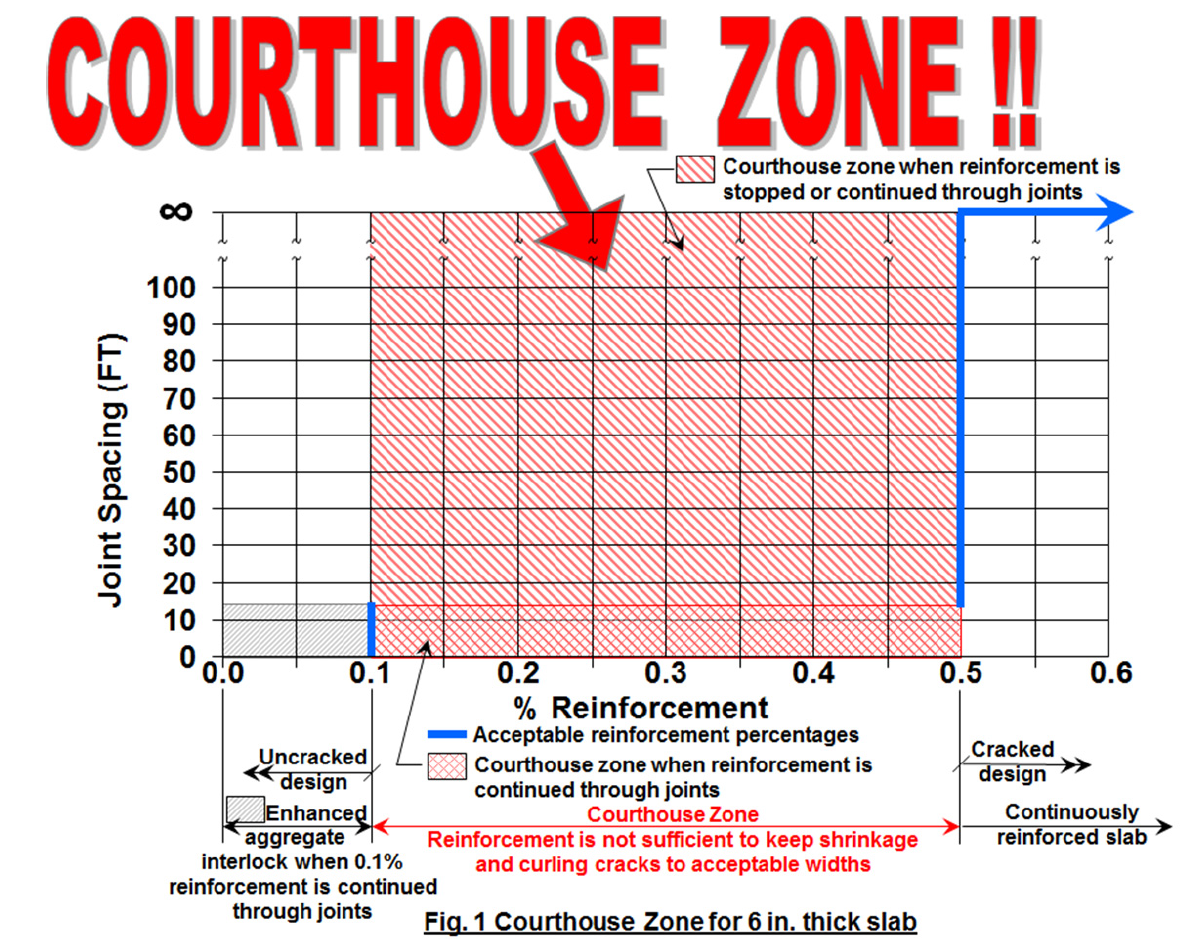
I agree with them about the zone. Steel between those two amounts is a bad place to be. In fact, that red band is essentially the steel range of the highway pavement type I'll get to in a minute, with 0.1% as its documented minimum, and the name "Courthouse Zone" fits its record. What interests me is the conclusion the floor industry drew from it: that the problem was too much steel, and the answer is less. That's the opposite of how we usually think about concrete and steel working together. My concern is that the acceptable choice on the left is a single point, and where that point came from.
You cannot build exactly 0.1%
I'll admit this one is personal. Whenever we talk about new ways to analyze and design slab thickness, someone asks a fair question: how do thickness tolerances affect the result? It has come up several times in conversations about SLABS. But I don't hear that question asked about enhanced aggregate interlock, which is the one slab system where the sensitivity to thickness has been stated outright, with a courthouse attached. ACI 360R-10 doesn't offer guidance on considering construction tolerances in design for any slab type, so there's no published source for the industry to lean on. So let's put the question where it matters most.
A steel ratio is the area of steel divided by the area of concrete. The steel is fixed by the bar size and spacing on the drawings. The concrete is not. It is set by the elevation of the subbase and the elevation of the finished surface, and neither is perfect.
The thickness tolerance discussion has been active in ACI for a few years. In the July 2021 issue of Concrete International, Eldon Tipping, Tim Manherz, Paul Beagley, Peter Ruttura, and Bruce Suprenant published thickness measurements from 32 slab-on-ground placements collected for ACI Committee 330. For level, hard-troweled slabs, the kind of interior floor this detail is used on, the thickness standard deviation was about 0.35 in. (8.9 mm) from contractors who volunteered their data, which the authors describe as the better half of the industry. An earlier data set collected from slabs with thickness problems showed a standard deviation of about 5/8 in. (16 mm), with the average slab 3/8 in. (9.5 mm) thinner than specified. The authors propose rating thickness control from excellent to poor, with "fair" at a standard deviation of up to 0.53 in. (13 mm), and recommend an individual-core tolerance of 1 in. (25 mm) below specified for these floors. ACI 117 currently allows the average to be 3/8 in. (9.5 mm) thin and an individual core to be 3/4 in. (19 mm) thin.
Run those numbers through the steel ratio (Figure 2). A 6 in. (150 mm) slab designed at exactly 0.100% steel is at 0.107% wherever it is 3/8 in. (9.5 mm) thin, 0.114% where it is 3/4 in. (19 mm) thin, and 0.120% where it is a full inch thin. Thicker slabs are less sensitive, but not by much: at 3/4 in. (19 mm) thin, a 7 in. (180 mm) slab is at 0.112% and an 8 in. (200 mm) slab at 0.110%.
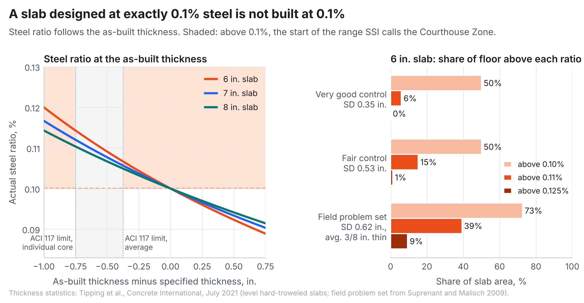
And because the target is a point, it cuts both ways. Where the slab is thick, the steel ratio drops below 0.1%, into the part of the chart meant for short joints and no tied run. Where it's thin, it climbs toward the Courthouse Zone. Statistically, if the average thickness is right on target, half of every floor is above 0.1% and half is below. Even with very good thickness control, about 40% of a 6 in. (150 mm) floor is more than 5% off 0.1% in one direction or the other. With the field-problem data, it's about 70%, and almost 10% of the floor is above 0.125%.
Thickness is not the only variable. Wherever a lap splice falls under a sawcut, the steel crossing that joint is doubled for the bars in the lap. Bars shift during placement. And if the bars are Grade 80 instead of Grade 60, 0.1% steel pulls across a joint as hard as Grade 60 at about 0.13%, which is well inside the zone.
None of this is a new idea, by the way. Twenty years ago, Frank McCullough's team at the University of Texas, working for TxDOT, recommended setting thickness tolerance as a percentage of design thickness instead of a fixed number, partly so nondestructive testing could replace cores. And design reliability, a basic input in pavement design, exists precisely because what gets built isn't what was drawn. The most probable as-built performance is at 50% reliability, not at the higher reliability we design to. ACI 360R-10 doesn't contain the word "reliability" once. Its text uses some form of "tolerance" 18 times, compared with 41 in ACI 330's guide for industrial site paving.
So a design point at exactly 0.1% is not one a contractor can build to. If 0.1% works and 0.11% puts the designer in court, the detail has no tolerance. I don't think the real behavior changes that sharply at 0.1%. Nothing in the mechanics makes 0.1% special; it just happens to be a nice round number. What are the odds? I think the restraint grows steadily with the steel, which is exactly why the detail should not depend on a single number.
The 97% the steel doesn't touch
Here's the part I think gets lost. ACI 360R-10 justifies 0.1% with a calculation (its Table 6.2) showing that the steel restrains under 3% of the concrete's shrinkage. That's a structural engineer's way of looking at it, and it's correct as far as it goes. But it means about 97% of the shrinkage is still there. It has to go somewhere.
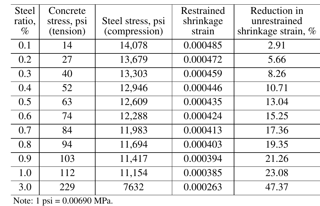
The whole point of the steel is to keep the sawcut joints tight so aggregate interlock keeps working. If those joints stay tight by design, then by design, all that movement has to go to the doweled joints at the ends of the run, the construction joints around each placement, up to 125 feet (38 m) apart. That only works if nothing gets in the way: base friction, a misaligned or locked dowel at the doweled joint, or an as-built steel ratio a little above or below 0.1%. When something does get in the way, one or two sawcuts open wide and take the movement instead. That's the dominant joint. In a 2007 article, Walker and Holland traced dominant joints to uneven base restraint and "differences in slab thickness," and said relying on aggregate interlock takes confidence in "the anticipated construction tolerances." ACI 360R-10 warns about dominant joints, and its own rules for this detail require the doweled joint precisely because the tied joints may not open.
Compare that with the two systems on either side. In a jointed plain slab, every joint takes its own share. In a continuously reinforced slab, the steel forces the movement into lots of fine cracks. This one asks the same light steel to hold the joints closed and still let the run move. It's a confused system, and confused systems perform more variably for the same inputs. Variability costs the owner money over the life of the floor.
The highway version of this detail
The roadway industry tried nearly everything with concrete pavements over the last century, and it did so on a scale no floor program will ever match: tens of thousands of lane miles, decades of condition surveys, and federally funded performance studies. Pavement engineers call a jointed slab with a small amount of distributed steel a jointed reinforced concrete pavement, or JRCP.
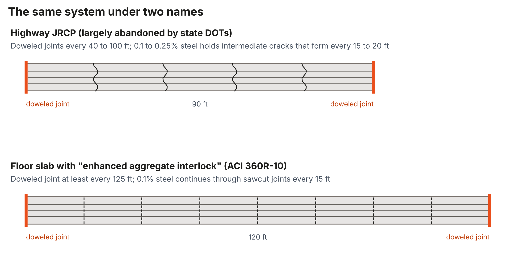
JRCP was the common way to build concrete highways for much of the 20th century. Joints were spaced 40 to 100 feet (12 to 30 m) apart, and anywhere from less than 0.1% to about 0.25% steel was placed to hold together the intermediate cracks that formed every 15 to 20 feet (4.6 to 6.1 m) between them. Doweled joints at the ends of each panel were expected to do the opening and closing. Notice that the steel was a range, not a number. Agencies never settled on one magic percentage, which is part of the story: the FHWA study found sections at 0.08% to 0.09% deteriorating and sections at 0.15% to 0.20% doing fine.
Put that next to the floor detail (Figure 4). A doweled joint at most every 125 feet (38 m), with a light layer of steel holding together the sawcut cracks every 15 feet (4.6 m) between them, is a JRCP panel with its intermediate cracks sawed in a straight line. The only real differences are that the floor detail cuts the cracks instead of letting them form and uses the low end of the JRCP steel range.
The 0.1% figure also shows up in highway practice, with a very different meaning. PCA's 2008 Concrete Floors on Ground, the most widely used slab-thickness reference in the U.S., says it plainly in its chapter on reinforcement: "In an FHWA study of jointed concrete pavement performance, pavement sections with more than 0.1% reinforcing steel exhibited less deteriorated transverse cracking," and "the study recommended using a minimum of 0.1% reinforcing steel based on cross-sectional area, with larger amounts required for harsher climates and longer slabs." That study was the FHWA's Performance of Jointed Concrete Pavements, published in 1990. In other words, on the roads 0.1% was a minimum for JRCP, the least steel that kept the cracks from falling apart, with more recommended for tougher conditions. I haven't found a published derivation of 0.1% for floors. My guess is it got there the way a lot of floor details did, by trial and error in the market, carrying JRCP practice over to slabs, with the Table 6.2 calculation used later to explain why it seemed to work. Either way, the floor detail sits at the low end of the steel range for a pavement laid out just like it.
What the highway agencies decided
The roads did not settle the JRCP question by argument. They settled it by watching pavements age. Intermediate cracks opened, steel corroded or ruptured at the cracks, and the cracks faulted and spalled. The steel yielded because there wasn't enough of it for the job. The FHWA study's own example of locked-up dowels, on I-94 in Minnesota, had 0.08% to 0.09% steel, which the researchers called inadequate for the climate. Meanwhile, the sections with more than 0.1% steel, most of them at 0.15% to 0.20%, performed very well regardless of joint spacing, base type, or dowel coating. On the roads, steel in the Courthouse Zone range was the fix, not the problem. To be fair, a road is designed to crack between its joints, so a tight crack counts as a success there, and a floor owner usually sees any crack outside a joint as a defect. But the roads still show that more steel, not less, is what kept those cracks tight. The agencies moved to the two types on either side of JRCP: short-jointed plain pavement, which removes restraint instead of fighting it, and continuously reinforced pavement, which uses enough steel to control every crack.
By the time I was at ACPA, almost every state had stopped designing JRCP. When the national mechanistic-empirical design method (now AASHTOWare Pavement ME) was developed, it covered jointed plain and continuously reinforced pavement only; its manual of practice states that JRCP pavements "were not directly considered in the MEPDG development and cannot be designed using this procedure." Texas held on longer than most, until its own review of performance data reached the same conclusion. Its pavement manual now says JRCP "is no longer endorsed by the department," citing past difficulty in finding effective ways to rehabilitate it.
It's worth being clear about what that history does and doesn't say. JRCP worked. It worked well enough that local engineers defended it hard, and I sat in a room in Texas while they did. The conversation only moved when it got past "it worked" to "but not as well as the alternatives," by comparing performance data across pavement types instead of judging one type only against itself. That's the bar the slab industry should hold itself to, for every part of the slab system: the joints that rely on light steel, not just the newest ideas on the table.
That is the context in which I read the Courthouse Zone chart. SSI's acceptable point on the left, 0.1% steel through the joints, sits at the bottom of the range that highway agencies tested at scale and walked away from. The right side, 0.5% and up, is essentially continuously reinforced pavement. The unreinforced option with closely spaced joints is jointed plain pavement. The highway industry kept the two ends and dropped the middle, and it drew the middle a lot wider than 0.1% to 0.5%.
Why the slab industry borrowed so much, and why it should borrow this too
PCA's 2008 thickness chapter is candid about how much floor design owes to highways. It says the method rests on "extensive data from many years of laboratory and field research and testing from highway pavement engineering," that "there are many similarities between an unreinforced road pavement and a plain concrete floor slab," and that "stress, deflection, and fatigue analytical approaches of pavement design are applicable to slabs on ground." The charts, the k-value, the joint factors, and the aggregate interlock data in ACI 360R-10 all came from pavement research. Floors are studied far less than roads, so the borrowing makes sense.
What I cannot explain is why floor design has been moving toward the one highway practice that highway agencies decided not to keep. Part of it, I think, is habit. Many engineers have never designed an unreinforced concrete element, and to them a slab without steel feels wrong. Some see light steel as insurance against poor or heaving soils. The highway experience is not encouraging on that point either: steel holds cracks together after they form, but it does not stop them from forming, and pavement engineers learned to fix support problems at the source, in the subgrade and subbase, rather than by adding steel to the slab above them. ACI 360R-10 says the same in its own way, by making uniform support the foundation of every thickness method in the guide.
What to do instead
None of this means a floor with 0.1% steel through the joints is certain to fail. It means the detail has the same weaknesses as the pavements it resembles, and very little tolerance for the way floors are actually built.
If you are designing or specifying a jointed industrial floor, the road experience points to a few practical choices:
- Use the ends, not the middle. Design a jointed plain slab with joint spacing that controls restraint and dowels where loads cross joints, or design a continuously reinforced slab with enough steel to control every crack. Treat anything in between as a deliberate choice that needs its own analysis.
- If you use light steel through the joints, do not treat 0.1% as a precise target you'll hit. Check the steel ratio at the thinnest and thickest slab the tolerances allow, account for laps and bar grade, and expect the doweled joints at the ends of each run to open much more than the sawcuts.
- Fix support problems in the soil. Steel does not make up for nonuniform or expansive subgrade. Proof-roll, compact, and stabilize instead.
- Specify and measure thickness. Tipping and his co-authors show that thickness control varies widely between contractors. For a detail whose performance depends on the steel ratio, thickness tolerance is part of the structural design.
- Estimate joint openings. ACI 360R-10 already says that where aggregate interlock carries the load, joint spacing should come from an evaluation of how wide the joints will actually open. That takes a model of the whole run of panels. The Slab Designer's JOINTS model is being developed to handle that task.
The highway industry paid for these lessons with decades of performance data. The floor industry does not need to pay for them again.
Sources
ACI Committee 360, ACI 360R-10, Guide to Design of Slabs-on-Ground, American Concrete Institute, Farmington Hills, MI, 2010. Section 6.2.
ACI Committee 117, ACI 117-10 (Reapproved 2015), Specification for Tolerances for Concrete Construction and Materials, American Concrete Institute, Farmington Hills, MI.
AASHTO, Mechanistic-Empirical Pavement Design Guide: A Manual of Practice, Interim Edition, American Association of State Highway and Transportation Officials, Washington, DC, 2008.
Farny, J. A., and Tarr, S. M., Concrete Floors on Ground, EB075, fourth edition, Portland Cement Association, Skokie, IL, 2008. Chapters 5 and 6.
Smith, K. D., Peshkin, D. G., Darter, M. I., and Mueller, A. L., Performance of Jointed Concrete Pavements, Volume III: Summary of Research Findings, FHWA-RD-89-138, Federal Highway Administration, 1990.
Kim, S.-M., and McCullough, B. F., Acceptable Concrete Pavement Thickness Tolerance, Project Summary Report 0-4382-S, Center for Transportation Research, The University of Texas at Austin, 2004.
Texas Department of Transportation, Pavement Manual, Section 4.7, Jointed Reinforced Concrete Pavement (JRCP).
Tipping, E., Manherz, T., Beagley, P. J., Ruttura, P. J., and Suprenant, B. A., "Establishing Thickness Tolerances for Parking Lot Slabs," Concrete International, Vol. 43, No. 7, July 2021.
Walker, W. W., and Holland, J. A., "Stay out of the Courthouse Zone," Engineering Bulletin, Structural Services, Inc., 2016.
Walker, W. W., and Holland, J. A., "The Hidden Cost of Aggregate Interlock," Concrete Construction, February 2007.
Smith, K. D., Peshkin, D. G., Darter, M. I., Mueller, A. L., and Carpenter, S. H., Performance of Jointed Concrete Pavements, Volume I: Evaluation of Concrete Pavement Performance and Design Features, FHWA-RD-89-136, Federal Highway Administration, 1990.
Related in This Series
- Technical paper on this topic: Light Reinforcement Through Sawcut Joints: Tolerances and the JRCP Record
Thickness tolerances push as-built steel ratios past 0.1%, and the highway record of JRCP shows where that detail leads.
- A Little Steel Through the Sawcut Is Not as Harmless as the Table Says
The 0.1% limit for continuous steel through sawcuts rests on a table that answers a different question than the joints ask.
- Your Warehouse Floor Is Not a Runway
Why an airport design method ended up sizing forklift floors, and why matching inputs is not the same as matching the problem.
- Spec Building Floors: Why Undoweled, Doweled, and 0.1% Steel Slabs Should Not Share One Thickness
The joint detail changes how thick a spec building slab needs to be, and the cost numbers say doweling pays.
- If You Can't Model It, You Can't Prevent It
A plain-language summary of our Concrete International and Concrete articles, and why, in our rack example, the highest stress is where the legacy methods don't look.
Revision history
- November 4, 2026: Corrected the reading of the Courthouse Zone (exactly 0.1% is a single acceptable point, not an upper limit); added where the other 97% of the shrinkage goes, the thickness tolerance question, and Table 6.2; added the Courthouse Zone figure; added the FHWA findings on steel percentage and dowel lockup and Walker and Holland's link between thickness and dominant joints; corrected the tolerance count; clarified that the doweled joints are at the ends of each placement.
- November 3, 2026: Added the point that the JRCP decision rested on comparing performance across types; completed references; added metric units and links to other pieces in the series.
- November 2, 2026: First published on slabs.design/knowledge.
To cite this article, use the citation printed in the PDF. It includes the revision date, so readers can match your citation to the text you read.