Article|TSD-12A
If You Can't Model It, You Can't Prevent It
Two magazines, two design traditions, one conclusion: the methods we size floors with check one face of the slab, assume it lies flat on the ground, and use the strength of a beam.
Robert Rodden (The Slab Designer, LLC); Juan Pablo Covarrubias (TCPavements-FORTA)
The Slab Designer, LLC | Published November 4, 2026
Where does a warehouse floor crack under a row of loaded racks?
If you said "under the rack legs," you're in good company. That's where the design methods look. In the example we published, it's not where the highest stress is.
Two magazines in year one
First, a little bragging, because we think it means something. In 2026, our first year in business, The Slab Designer and our co-authors got two articles into two of the largest magazines covering concrete in the world: "Mechanistic-Empirical Design of Concrete Slabs-on-Ground" in the American Concrete Institute's Concrete International in July, and "Updating Design Methods for Modern Concrete Slab Systems" in the Concrete Society's Concrete in September. The author lists include Jeff Roesler (Illinois), Lev Khazanovich and Jorge Olavarría (Pittsburgh), Nigel Parkes, and the two of us.

Editors don't pick articles to be nice. They pick them because their readers care. Two of them, on two continents, picked this topic in the same year. We take that as a sign a lot of people are asking the same question we are: have the design methods for industrial floors kept up with the floors?
Together, the two articles tell the background of SLABS. Here's the short version.
Two traditions, one assumption
In the United States, floor thickness design traces to Westergaard's 1926 solutions for a load on a slab that sits in full contact with its support. The three methods in ACI 360R-10 (PCA, now ACA; WRI; and the Corps of Engineers) all carry that assumption, and the guide says what happens when it isn't true. Section 14.13: the methods "give erroneous results for slab thickness where the slab is not in contact with the subgrade."
Outside ACI's world, the guide is usually the Concrete Society's TR34, which sizes slabs with yield-line theory through Meyerhof's 1962 solutions, and checks line loads and uniform loads with Hetényi's beam on an elastic foundation. Different theory, same starting point. Meyerhof says plainly that his analysis assumes full contact between base and slab and no curling.
So one tradition calculates an elastic stress and the other calculates a collapse load, but both assume a slab lying flat on the ground. Indoor slabs don't. They dry from the top and curl up at their edges and corners. That isn't a special case; it's the normal case.
Collapse load or first crack?
TR34 answers a good question: what load collapses the slab? It assumes the bottom of the slab has already cracked under the load and let the fibers or fabric carry moment, and it caps the top at the cracking moment of plain concrete.
But that's not what owners call about. How many times have you heard of a callback for a complete collapse? They call about joints falling apart, corner cracks, faulting, curl, slabs that move under the trucks, and rough surfaces. As the Concrete article puts it, those are conditions yield-line theory "was never expected to predict." Owners expect a floor without cracks, top or bottom. So the question that should govern design is: at what load does the first crack show up, with the curl, the lost support, the joints, and the actual slab size?
A beam is not a slab
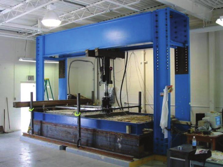
Both traditions get their strength from a beam. We break a small beam on two supports, and that number becomes the strength of the floor. But a slab-on-ground isn't a small beam on two supports. It's supported everywhere, it can shift load around, and it carries more than the beam test says. Even the beam number isn't one number: center-point and third-point tests have been known for about 100 years to differ by 15 to 25%. Tests on full-scale slabs, plain and with fibers, have shown that using the beam strength for the slab is a "gross and overly conservative simplification," in the Concrete International article's words.
That matters more than it sounds. If you took honest stresses (with curl, at the joints) and compared them with beam strength, you'd predict cracked floors in a lot of buildings that are doing fine. Getting both the stress and the capacity right is the only way we've found for the math to start explaining how floors have actually performed.
The picture we always come back to
Here's the example we talk through most, from the Concrete article. Back-to-back racks on a 4 x 3 panel system, slabs curled, analyzed with ISLAB2000.
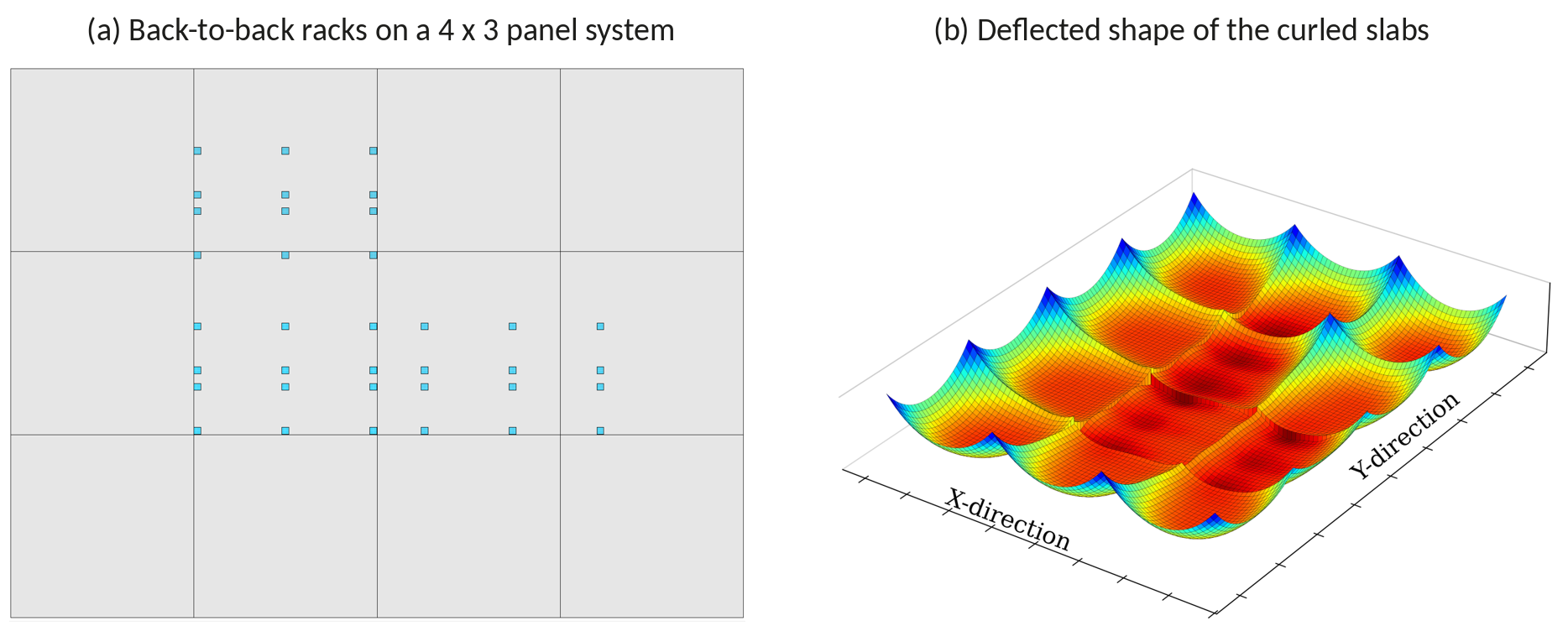
Now look at the two faces of the slab.
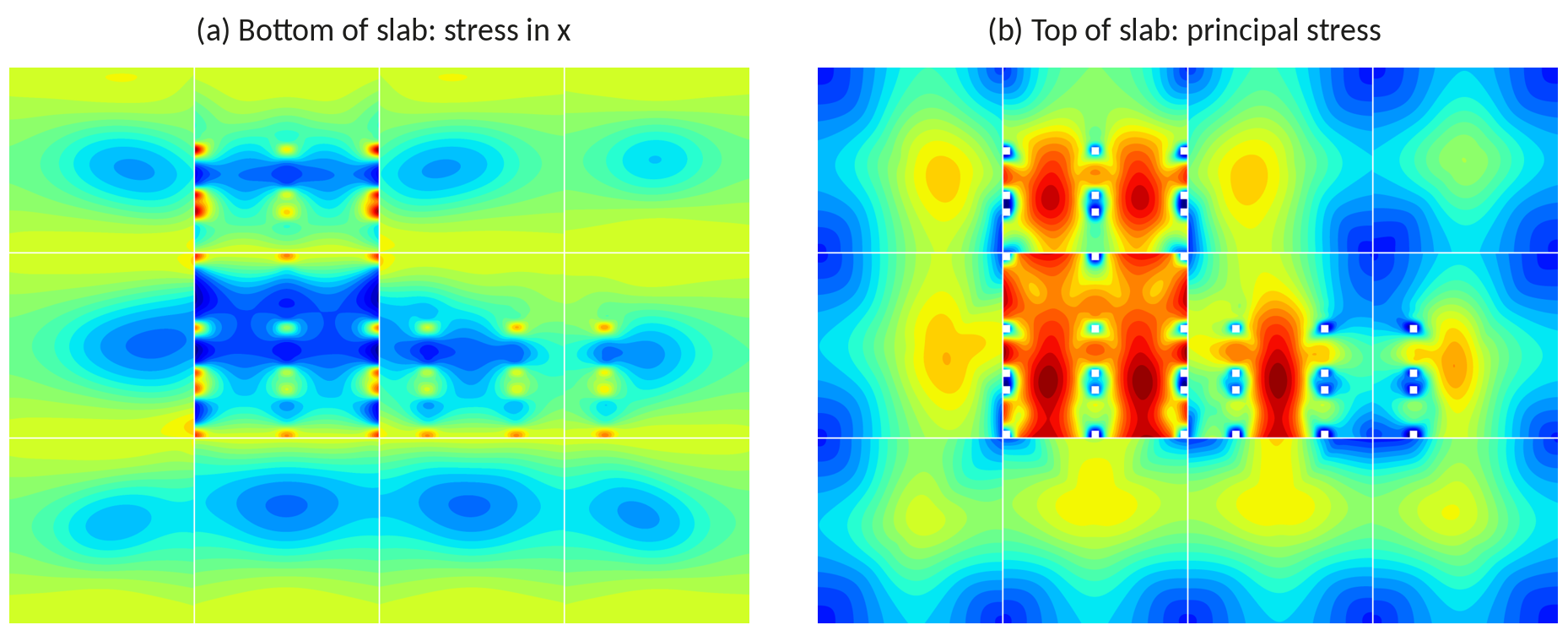
The legacy methods check the bottom of the slab, bottom-up cracking. That's usually in the middle of the slab under the load, and sometimes at the edge of a flat slab. Sure enough, the bottom plot (a) shows tension under the rack legs.
But in this example, the plot with the highest stresses and the most red is (b), the top of the slab. That's top-down cracking risk, and it's between the rack legs, not under them, and along the joints. The Westergaard methods don't calculate top tension at all. Meyerhof's mechanism has a crack ring at the top, but around one load, on a slab flat on the ground. Neither one calculates what's going on in that aisle.
If a method can't model it, it can't design against it. All it can do is rely on the safety factor being big enough, and often it is.
Wrong in both directions
This cuts both ways, and that's the part we like about it. Where curl is significant and joints don't share load well, the traditional methods underpredict the critical stress by 20 to 50%. Where slabs are well supported and doweled, they overpredict by 15 to 25%, and you're paying for concrete you didn't need. In a comparison of seven common slab systems run through SLABS, the thickest slab, an unreinforced 10 in. (250 mm) section, could be 30% thinner once load transfer at the joints and curl reduction were considered. Thickness turned out to be a poor indicator of performance.
A method that can't model curl, slab size, joints, and loss of support has no way of knowing the real factor of safety of the floor it designs. It might be high. It might be gone.
Pavements already did this
None of this is new to pavement engineers. Highways and airfields hit the same wall decades ago, and instead of adding more adjustments to old equations, they moved to mechanistic-empirical design on finite element analysis. AASHTO's Pavement ME uses neural networks trained on ISLAB2000 to model slab size, curl, support, loss of support, and joint load transfer.
SLABS takes the same path for floors. It keeps Westergaard's plate on springs as the foundation and adds what the old methods left out: curl as an input (EBITD, measured or converted from a curl number), layered support as a composite k-value, joints and dowels modeled explicitly, real loads (lift trucks, rack posts with back-to-back interaction, storage, seismic) on real panel sizes, fibers and post-tensioning as inputs, and a slab capacity instead of a beam strength. A neural network trained on more than 1.3 million ISLAB2000 runs gives finite element answers in milliseconds, within 2% on peak stress.
It also turns up a few surprises. A stiffer base lowers the load stress, but it makes curl worse, so "a low k-value is conservative" may not be true once curl is in the model.
What to ask on your next project
- Which face of the slab was checked? Top and bottom, or just the bottom under the load?
- Where are the racks relative to the joints, and was the top of the slab between the legs checked?
- How was curl handled: as an input, or as a paragraph in the guide?
- Is the stress compared with a beam strength or with the capacity of a slab?
- Were the joints and their load transfer modeled, or assumed?
- If you're leasing a building, did anyone certify that differential deflection across the joints under your trucks meets ACI 360R-10's guidance, 0.010 in. for small, hard wheels and 0.020 in. for larger rubber wheels?
As the Concrete article closes, the question isn't whether these things matter anymore. It's whether we keep relying on methods that don't consider them. We don't think we have to.
Sources
Covarrubias, J. P., Rodden, R., Roesler, J., Khazanovich, L., Olavarría, J., and Parkes, N., "Mechanistic-Empirical Design of Concrete Slabs-on-Ground," Concrete International, Vol. 48, No. 7, July 2026, pp. 45-53.
Roesler, J., Covarrubias, J. P., Khazanovich, L., Olavarría, J., Parkes, N., and Rodden, R., "Updating Design Methods for Modern Concrete Slab Systems," Concrete, The Concrete Society, Vol. 60, No. 7, September 2026, pp. 14-17.
ACI Committee 360, ACI PRC-360R-10, Guide to Design of Slabs-on-Ground, American Concrete Institute, 2010. Section 14.13.
The Concrete Society, Technical Report 34, Concrete Industrial Ground Floors, 4th ed., 2013.
Meyerhof, G. G., "Load Carrying Capacity of Concrete Pavements," Journal of the Soil Mechanics and Foundations Division, ASCE, Vol. 88, No. SM3, 1962.
Westergaard, H. M., "Stresses in Concrete Pavements Computed by Theoretical Analysis," Public Roads, Vol. 7, No. 2, 1926.
Covarrubias, J. P., Parkes, N., and Rodden, R., "Concrete Slab-on-Ground Thickness Requirements from Modern Design," For Construction Pros, July 20, 2026.
Related in This Series
- Technical paper on this topic: From Westergaard and Meyerhof to Mechanistic-Empirical Design
Summarizes the 2026 Concrete International and Concrete articles that set out why the Westergaard and Meyerhof methods fall short for modern floors and how the SLABS framework addresses it.
- The Design Guide a New Engineer Can't Design From
A new engineer follows ACI 360R-10 step by step and finds the places it raises an issue and stops.
- The Floor Design Guide That Calls Its Own Results Erroneous
What owners should know about the trap built into the industry's main slab design guide.
- Your Warehouse Floor Is Not a Runway
Why an airport design method ended up sizing forklift floors, and why matching inputs is not the same as matching the problem.
- The Roads Already Ran the 0.1% Experiment
Light steel through the joints has a name in highway engineering, and most DOTs stopped building it decades ago.
To cite this article, use the citation printed in the PDF. It includes the revision date, so readers can match your citation to the text you read.