Technical Paper|TSD-10TP
Light Reinforcement Through Sawcut Joints in Slabs-on-Ground: Construction Tolerances and the Highway Record of Jointed Reinforced Concrete Pavement
The Slab Designer, LLC | Published November 2, 2026 | Revised November 4, 2026
Abstract
ACI 360R-10 permits 0.1% deformed reinforcement continued through sawcut contraction joints as "enhanced aggregate interlock," with doweled joints at a maximum spacing of 125 ft (38 m) and a uniform slab thickness. Industry guidance has since described reinforcement ratios between 0.1% and 0.5% as a "Courthouse Zone" to be avoided, and marks exactly 0.1% continued through the joints as the one acceptable choice short of continuous reinforcement. That is a single point, not an upper limit, and it is stated without a tolerance or a mechanical basis. This paper examines it from three directions. First, because the steel ratio is set by bar size and spacing while the concrete area is set by the as-built thickness, the ratio varies with construction tolerances. Using thickness statistics for level hard-troweled slabs reported by Tipping et al. (2021), a 6 in. (150 mm) slab designed at exactly 0.100% is at 0.107% where it is 3/8 in. (9.5 mm) thin, 0.114% at the ACI 117 individual-core limit, and 0.120% at a 1 in. (25 mm) deficiency; with very good thickness control, about 40% of the floor departs from 0.100% by more than 5% in one direction or the other, and with control typical of problem projects about 70% does. Lap splices and higher bar grades raise the effective ratio further. Second, the steel restrains only about 3% of free shrinkage by the guide's own calculation; the other 97% must be delivered to the doweled joints, and base friction, dowel condition, and any departure from the design ratio change how it divides, which is consistent with the guide's caution about dominant joints. Third, the layout of the detail, long spacing between doweled joints with light steel holding closely spaced cracks between them, is that of jointed reinforced concrete pavement (JRCP). The guide supports 0.1% with a section-level shrinkage calculation from structural design, and the figure coincides with the FHWA minimum steel for JRCP that PCA's floor manual cites; the highway agencies behind that minimum subsequently moved away from JRCP in favor of jointed plain and continuously reinforced pavement. The paper recommends treating restraint from continued reinforcement as a continuous function of tie force rather than a threshold, verifying the steel ratio at both thickness tolerance limits, and drawing on the highway record when selecting slab type.
Keywords: slab-on-ground, enhanced aggregate interlock, jointed reinforced concrete pavement, thickness tolerance, reinforcement ratio, joint restraint
Introduction
Industrial floors and other slabs-on-ground are commonly built as jointed slabs in which drying shrinkage is accommodated by sawcut contraction joints. Load is carried across the joints by dowels, by aggregate interlock on the cracked faces, or by both. One detail that has gained use over the last two decades continues a light layer of deformed reinforcement through every sawcut, so that the bars hold the crack faces together and maintain aggregate interlock without dowels. ACI 360R-10 (1) calls this "enhanced aggregate interlock" and limits the steel to 0.1% of the slab cross section.
A companion paper in this series (2) examined the restraint mechanics of the detail: the section-level shrinkage solution used to support the 0.1% limit, the force the bars can transfer across a joint compared with base friction, and the redistribution of joint opening toward doweled joints. This paper addresses two further questions. The first is practical: whether a ratio as specific as 0.1% can be achieved in construction, given measured variation in slab thickness, and what happens to the shrinkage the steel does not restrain. The second is historical: where the 0.1% figure came from, and what the highway pavement industry, which built the same system at a far larger scale, learned about it.
Background
The ACI 360R-10 Provision
Section 6.2 of ACI 360R-10 (1) states that continuing 0.1% deformed reinforcement through sawcut contraction joints, with the joint spacing of its Fig. 6.6, "has been used successfully by some designers to provide load-transfer capability without using dowels." It requires that joints be spaced per Fig. 6.6; that the reinforcement be placed above mid-depth but below the sawcut; that a construction or sawcut contraction joint with a load-transfer device be placed at a maximum of 125 ft (38 m), which "forces activation at these joints when the other joints with the deformed reinforcement do not activate"; that all sawcut joints be cut with early-entry saws; and that "the slab should be a uniform thickness." It cautions that larger percentages "restrain joints from opening as the slab shrinks during drying, and this increases the probability of out-of-joint random cracking."
The Courthouse Zone
Walker and Holland (3) characterize the transition between unreinforced and reinforced slab behavior in terms of litigation risk. Their Fig. 1, drawn for a 6 in. (150 mm) slab, plots joint spacing against reinforcement ratio and marks the acceptable reinforcement percentages in blue (Figure 1). One is 0.5% or more of continuous reinforcement, drawn for joint spacings from about 15 ft (4.6 m) to unlimited, a cracked design without sawcut joints in which the steel controls the width of the resulting cracks, consistent with ACI 360R-10 Section 8.3 and the ACI 224R-01 observation that crack control generally requires more than about 0.6% (4). The other is a single ratio: enhanced aggregate interlock with 0.1% continued through sawcut joints, drawn as a short vertical line for joint spacings up to about 15 ft (4.6 m), which "allows joints to activate" while maintaining joint stability. Ratios below 0.1% at those spacings are shown in grey as an uncracked design. The text of the bulletin states the 0.1% and 0.5% values without reference to thickness; the 6 in. (150 mm) thickness enters the figure through the joint spacing of about 15 ft (4.6 m), close to the ACI 360R-10 Fig. 6.6 spacing for that thickness. The bulletin does not derive the 0.1% value. For the detail it cites ACI 360R-10, which supports 0.1% with the calculation discussed below. Ratios between 0.1% and 0.5% are shaded as the "Courthouse Zone," because such amounts "are too high to allow joint activation to occur but are not sufficient to control crack widths to an acceptable level for most owners." The bulletin identifies three common routes into the zone: the subgrade drag equation, ACI 318 minimum reinforcement of 0.18%, and steel selected without calculation, for which it gives the example of a 6 in. (150 mm) slab with No. 4 bars at 18 in. (0.185%).
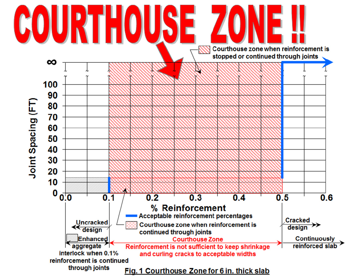
The two documents frame the number differently. ACI 360R-10 treats 0.1% as an upper bound, stating that larger percentages should not be continued through joints (1). The figure does not define a window below 0.1%. Its note describes enhanced aggregate interlock at 0.1%, not up to 0.1%, so the acceptable choice is the point itself, and an as-built ratio on either side of it is off the mark. The bulletin gives no tolerance on that value and no mechanical basis for why the point falls at 0.1% rather than a nearby value; that a boundary with no mechanical derivation should land on a round number is itself worth noting. The bulletin's observation that intermediate ratios perform poorly is consistent with the force criterion discussed in the companion paper (2) and with the highway record discussed below. Read against that record, the Courthouse Zone spans essentially the steel range of jointed reinforced concrete pavement, a range within which highway agencies never settled on a single percentage, with 0.1% as its documented minimum, and its name agrees with the performance that led highway agencies away from that pavement type. The bulletin's remedy is to stay at the bottom of the range; the highway remedy was to leave the range, either by removing the distributed steel or by adding enough to control every crack.
Origin of the 0.1% Figure
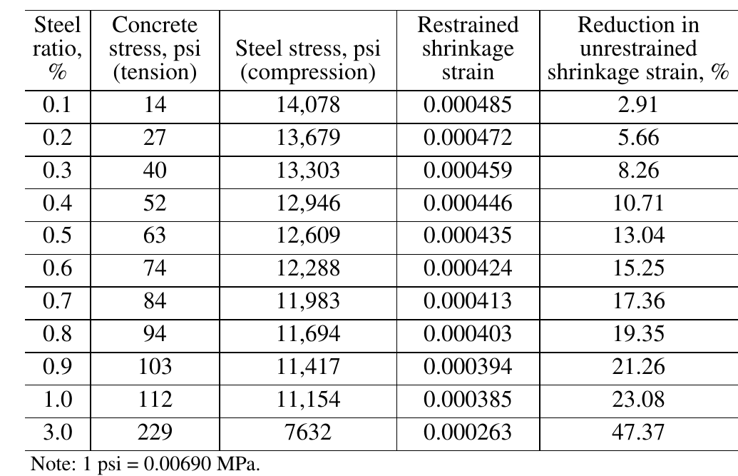
ACI 360R-10 supports the figure with its Table 6.2, a solution from Park and Paulay (20) for shrinkage restraint in an uncracked, symmetrically reinforced member, which shows that 0.1% steel reduces free shrinkage by just under 3%. The guide treats that reduction as minor and the restraint as acceptable (1). It is a structural engineer's argument: it asks how much the steel restrains the concrete and finds a ratio at which the answer is very little. The companion paper (2) shows that the calculation is correct within its assumptions but describes an uncracked member with no joints and no base friction, and that the computed restraint varies smoothly with the steel ratio. Nothing in it makes 0.1% different from 0.09% or 0.12%.
The same number appears in highway practice, with a different meaning. The PCA design manual Concrete Floors on Ground (5), in its discussion of distributed steel for jointed floors, notes that the subgrade drag formula often gives less than 0.1% steel and continues: "In an FHWA study of jointed concrete pavement performance, pavement sections with more than 0.1% reinforcing steel exhibited less deteriorated transverse cracking. Sections with less than 0.1% reinforcing steel often displayed a significant amount of deteriorated transverse cracking, especially in colder climates. As a result, the study recommended using a minimum of 0.1% reinforcing steel based on cross-sectional area, with larger amounts required for harsher climates and longer slabs." The study cited is the FHWA Performance of Jointed Concrete Pavements program (6, 21). Its evaluation volume states the finding directly: sections with more than 0.10% reinforcement "appear to have performed very well regardless of the joint spacing, base type, or dowel coating," and "a minimum of 0.10 percent reinforcement appears to be necessary to control transverse cracking, with higher amounts for extreme climatic conditions or stiff base course materials" (21, p. 135). Most of the well-performing reinforced sections in that comparison carried 0.15% to 0.20% steel (21, p. 135), squarely inside the range the Courthouse Zone tells floor designers to avoid. In highway practice, steel in that range was the remedy, not the problem. The comparison has a limit that should be stated: a JRCP pavement is designed to crack between its joints, so tight intermediate cracks count as success, while a floor owner usually treats any crack outside a joint as a defect. The highway data show that more steel kept cracks tight; they do not show that a floor with that steel will look the way its owner expects.
The floor detail and the highway minimum therefore share a number but not a basis. In highway practice, 0.1% was the least steel that kept intermediate cracks in JRCP from deteriorating, and more was recommended for harsher conditions. In the floor detail, it is the one acceptable amount, supported by a section-level calculation rather than by performance data. No published derivation of the 0.1% value for floors has been found. A plausible origin is the carryover of JRCP practice into slabs-on-ground through trial and error in the market, with the section-level calculation offered afterward in support; the analysis in this paper does not depend on which account is correct. What matters is that it sits at the low end of the JRCP steel range, in a system laid out like JRCP.
Sensitivity of the Steel Ratio to Slab Thickness
Formulation
For bars of area Ab at spacing s, the steel area per unit width is As = Ab/s, fixed by the drawings. The design ratio at the specified thickness ts is ρd = As/ts. At an as-built thickness ta, the actual ratio is
Common details are close to 0.1% but rarely exact: a No. 3 bar at 18 in. (460 mm) in a 6 in. (150 mm) slab gives 0.102%, at 16 in. (410 mm) in a 7 in. (180 mm) slab 0.098%, and at 14 in. (360 mm) in an 8 in. (200 mm) slab 0.098%. To isolate the effect of construction, the analysis below assumes ρd = 0.100% exactly.
If the as-built thickness is normally distributed with mean ts + MD and standard deviation σ, the fraction of slab area in which the actual ratio exceeds a value ρx is
where Φ is the standard normal distribution function.
Thickness Statistics
Tipping et al. (7) report thickness measurements from slab-on-ground placements collected by ACI Committee 330 and compare them with earlier data. For level hard-troweled slabs, the weighted average standard deviation in the ACI 330 data was 0.35 in. (8.9 mm), from contractors who volunteered data and who the authors judge to represent the better half of the population. An earlier data set compiled by Suprenant and Malisch (8), drawn from slabs with thickness problems, had a weighted average standard deviation of about 5/8 in. (16 mm) and a mean deviation of about −3/8 in. (9.5 mm). The authors propose levels of thickness control for level hard-troweled slabs ranging from excellent (below 0.30 in.) through very good (0.30 to 0.37 in.), good (0.38 to 0.45 in.), and fair (0.46 to 0.53 in.) to poor (above 0.53 in.), and recommend an individual-sample tolerance of 1 in. (25 mm) below specified thickness based on twice the upper limit of fair control. ACI 117 (9) currently limits the average of samples to 3/8 in. (9.5 mm) below specified and an individual sample to 3/4 in. (19 mm) below specified. The authors also note that subbase elevation, not the finished surface, dominates the variation.
One limitation of these data should be stated. The measurements come from placements collected through ACI Committee 330, whose scope is site paving, and the grading for such work may receive less attention than the subbase under an interior floor, in which case interior slabs would show tighter thickness control. That is possible, but it is equally possible that it is not; the same contractors and the same placing and finishing methods are often used for both. Thickness variation in interior slabs-on-ground needs to be measured and published. Some consultants likely hold enough data to answer the question, but in the slab-on-ground industry such data are usually treated as proprietary, so they are not available for others to examine or rely on. Until they are, the statistics used here are the best published basis available.
Results
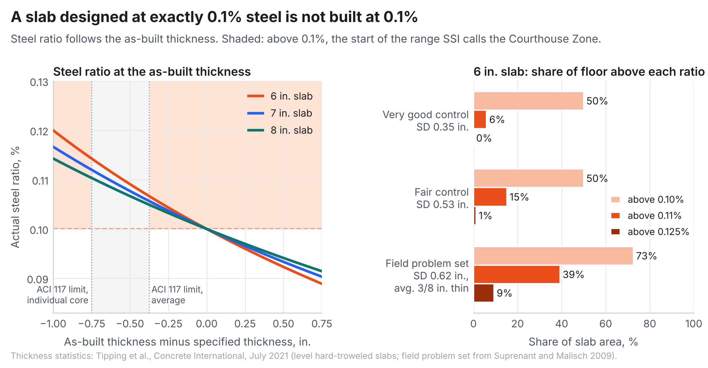
Table 1 gives the actual steel ratio from Equation 1 at thickness deviations spanning the tolerance range. At the ACI 117 average limit, the ratio in a 6 in. (150 mm) slab is 0.107%; at the individual-sample limit it is 0.114%, and at the 1 in. (25 mm) deficiency recommended by Tipping et al. as a tolerance it is 0.120%. The ratios for 7 and 8 in. (180 and 200 mm) slabs are lower but of the same order.
Table 1. Actual Steel Ratio, %, at As-Built Thickness for Slabs Designed at 0.100%
| Deviation, in. | −1 | −3/4 | −1/2 | −3/8 | −1/4 | 0 | +1/4 | +1/2 | +3/4 |
|---|---|---|---|---|---|---|---|---|---|
| 6 in. slab | 0.120 | 0.114 | 0.109 | 0.107 | 0.104 | 0.100 | 0.096 | 0.092 | 0.089 |
| 7 in. slab | 0.117 | 0.112 | 0.108 | 0.106 | 0.104 | 0.100 | 0.097 | 0.093 | 0.090 |
| 8 in. slab | 0.114 | 0.110 | 0.107 | 0.105 | 0.103 | 0.100 | 0.097 | 0.094 | 0.091 |
Table 2 applies Equation 2 for three levels of thickness control: the ACI 330 average (very good), the upper limit of fair, and the problem-project data. When the mean thickness equals the specified thickness, half the slab area exceeds 0.1% regardless of the standard deviation. With fair control, 15% of a 6 in. (150 mm) slab exceeds 0.11%. With the problem-project statistics, about 73% exceeds 0.1%, 39% exceeds 0.11%, and 9% exceeds 0.125%.
Table 2. Percentage of Slab Area Exceeding, or Within ±5% of, Selected Steel Ratios (Design Ratio 0.100%)
| Thickness control | Slab, in. | > 0.10% | > 0.11% | > 0.125% | Range at mean ± 2σ, % | 0.095 to 0.105% |
|---|---|---|---|---|---|---|
| Very good, MD 0, σ 0.35 in. | 6 | 50 | 6.0 | 0.0 | 0.090 to 0.113 | 61 |
| 7 | 50 | 3.5 | 0.0 | 0.091 to 0.111 | 68 | |
| 8 | 50 | 1.9 | 0.0 | 0.092 to 0.110 | 75 | |
| Fair limit, MD 0, σ 0.53 in. | 6 | 50 | 15.2 | 1.2 | 0.085 to 0.121 | 43 |
| 7 | 50 | 11.5 | 0.4 | 0.087 to 0.118 | 49 | |
| 8 | 50 | 8.5 | 0.1 | 0.088 to 0.115 | 55 | |
| Problem projects, MD −3/8 in., σ 5/8 in. | 6 | 73 | 39.3 | 9.3 | 0.087 to 0.137 | 31 |
| 7 | 73 | 33.8 | 5.1 | 0.089 to 0.130 | 36 | |
| 8 | 73 | 28.7 | 2.5 | 0.090 to 0.125 | 40 |
Other Sources of Variation
Thickness is not the only source. Where a lap splice crosses a sawcut, the steel area of the lapped bars is doubled at that joint; with staggered laps, a fraction of the bars at many joints is doubled. Bar spacing and chair height vary within placement tolerances. Bar grade changes the tie force for a given ratio: as shown in the companion paper (2), 0.1% of Grade 80 steel transfers the same force across a cracked joint as 0.133% of Grade 60, so that a limit intended to cap restraint is properly a limit on ρfy. These effects are additive with the thickness effect in Table 1.
Interpretation
The results do not show that a particular slab will crack randomly at 0.11% when it would not have at 0.10%. The restraint from continued reinforcement increases continuously with tie force (2), and nothing in the mechanics creates a step at 0.1%. What the results show is that a design defined by a single steel ratio, with the region above it treated as a known source of litigation, cannot be met in construction. With very good thickness control, about 40% of the floor departs from 0.100% by more than 5%; with fair control more than half does, and with the problem-project statistics about 70% does (Table 2). Where the slab is thin, the ratio moves above 0.1%, toward the Courthouse Zone; where it is thick, it moves below, into the region the bulletin associates with an uncracked design and short joint spacing rather than with long runs between doweled joints. The slab cannot meet the ACI 360R-10 condition of uniform thickness to the precision such a point implies. Either the acceptable point has width, in which case its bounds and their basis should be stated, or the detail has essentially no construction tolerance.
How thickness tolerance affects a design result is a question regularly raised about newer mechanistic-empirical thickness methods. It is rarely raised about this detail, although it is the one slab system for which sensitivity to as-built thickness has been stated explicitly, in the form of a warning about litigation. ACI 360R-10 offers no guidance on accounting for construction tolerances in design for any slab type, so at present the industry has no published basis for answering the question for the system most exposed to it. Walker and Holland's 2007 article identified differences in slab thickness as one cause of dominant joints (22).
Pavement design addressed this problem long ago through reliability. Design reliability accounts for the fact that as-built support, thickness, strength, and traffic will vary from the values assumed; the most probable performance of a built section is at 50% reliability, not at the higher reliability used in design. ACI 360R-10 does not contain the word "reliability," and its text, excluding front matter and references, uses some form of "tolerance" 18 times, compared with 41 times in ACI 330.2R-17 (18) counted the same way. Research for TxDOT two decades ago recommended expressing thickness tolerance as a percentage of design thickness rather than a fixed dimension, and found that acceptable tolerance increases with thickness (19). A reinforcement limit whose meaning depends on the as-built thickness is a natural candidate for the same treatment.
The Highway Record
Pavement Types
The highway concrete pavement industry has used three basic jointed and continuous types over the last century (10, 11). Jointed plain concrete pavement (JPCP) has no distributed steel and controls shrinkage cracking with closely spaced contraction joints, with or without dowels. Jointed reinforced concrete pavement (JRCP) uses longer panels between doweled joints and a small amount of distributed steel to hold together the intermediate cracks that form between them. Continuously reinforced concrete pavement (CRCP) has no transverse contraction joints and uses enough longitudinal steel, typically about 0.6% or more, to hold closely spaced cracks tight (12). Table 3 compares the three with the floor details that correspond to them.
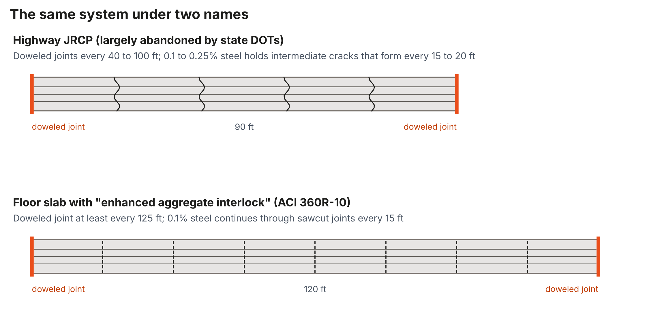
Table 3. Highway Pavement Types and Corresponding Slab-on-Ground Details
| Feature | JPCP | JRCP | CRCP |
|---|---|---|---|
| Transverse joint spacing | Typically about 15 to 20 ft | About 40 to 100 ft between doweled joints | None (end treatments only) |
| Crack pattern | Cracks at joints | Intermediate cracks about 15 to 20 ft apart | Cracks about 2 to 6 ft apart |
| Distributed steel | None | About 0.1 to 0.25% | About 0.6% or more |
| How shrinkage is accommodated | Jointing | Joint opening, with steel holding intermediate cracks | Many fine cracks |
| Current highway status | Most common type | Largely discontinued; not covered by the AASHTO mechanistic-empirical method | In use where long life is needed |
| Corresponding floor detail | Unreinforced slab with sawcut joints per ACI 360R-10 Fig. 6.6 | 0.1% steel through sawcut joints, doweled joint at 125 ft maximum ("enhanced aggregate interlock") | Continuously reinforced slab, 0.5% minimum per ACI 360R-10 |
The correspondence in the middle column is close. In JRCP, intermediate cracks form between doweled joints and are held by light steel; in the floor detail, sawcuts are placed where those cracks would form and are held by light steel, with a doweled joint at the end of the run. The floor detail uses the low end of the JRCP steel range and a somewhat longer distance between doweled joints.
Performance and the Move Away From JRCP
JRCP was widely built on the Interstate system and on other highways for much of the 20th century (10). Its documented problems were concentrated at the intermediate cracks and the doweled joints. Where the steel was light, or where it yielded, corroded, or ruptured, intermediate cracks opened, lost aggregate interlock, faulted, and spalled (17); the FHWA performance studies that produced the 0.1% minimum found deteriorated transverse cracking associated with low steel percentages, cold climates, and long panels (5, 6). PCA's floor manual adds that highway researchers attributed some of the poor performance to steel yielding caused by malfunctioning doweled joints (5). The FHWA evaluation's own example of dowel lockup, on I-94 in Minnesota, had only 0.08% to 0.09% reinforcement, which the authors judged "inadequate for the temperature extremes of the region"; the reinforcement design "was unable to accommodate the increased stresses of immobile joints" (21, p. 133). Read with the sections above 0.10% that performed well regardless of dowel condition, the variable the data tie most directly to deterioration is the steel percentage: the steel yielded because there was not enough of it for the conditions. The long panels also produced wide joint openings that were difficult to seal.
CRCP itself is evidence of how the industry read the JRCP record: when a small amount of steel in long jointed panels did not control the cracks, the response was to add much more steel and remove the joints entirely, not to keep the light steel. State agencies responded by moving to the two types on either side of JRCP: JPCP with shorter joint spacing, typically doweled on higher-volume routes, which is now the most common concrete pavement type (10), and CRCP where long life justifies its cost (12). Pavement Interactive summarizes the outcome: "In general, JRCP has fallen out of favor because of inferior performance when compared to JPCP and CRCP," and only a handful of agencies continue to use it (13). The national mechanistic-empirical design procedure developed under NCHRP Project 1-37A and adopted by AASHTO covers JPCP and CRCP; its manual of practice states that JRCP "were not directly considered in the MEPDG development and cannot be designed using this procedure" (14). The Texas Department of Transportation, among the last agencies to retain the type, states in its pavement manual that JRCP "is no longer endorsed by the department," citing past difficulty in selecting effective rehabilitation strategies (15). In the author's experience at the American Concrete Pavement Association, TxDOT's own review of performance data contributed to that decision.
Transfer of Highway Practice to Floors
The floor design literature has drawn heavily on highway research. PCA's floor thickness method rests, in its own words, on "extensive data from many years of laboratory and field research and testing from highway pavement engineering," and PCA notes that "there are many similarities between an unreinforced road pavement and a plain concrete floor slab" and that "stress, deflection, and fatigue analytical approaches of pavement design are applicable to slabs on ground" (5). The k-value, the thickness charts derived from Westergaard's pavement solutions, the joint factors, and the aggregate interlock data cited in ACI 360R-10 (16) all originated in pavement research. PCA's joint factor for loads at joints, introduced in its 2001 edition, was likewise based on finite element analysis with ILLI-SLAB, a program developed for pavements (5).
Against that background, the adoption of light continuous reinforcement in jointed floors runs in the opposite direction from the highway experience. Several factors may contribute. Many structural engineers have never designed an unreinforced concrete element, and a jointed slab without steel can appear deficient by comparison with other concrete work. Light steel is also sometimes specified as insurance against nonuniform or expansive subgrade. On that point the highway record is consistent: distributed steel holds cracks together once they form but does not prevent them, and pavement practice addresses nonuniform support at its source through subgrade preparation, stabilization, and drainable or stabilized subbases rather than through reinforcement (10, 11). ACI 360R-10 itself makes uniform support a premise of every thickness method it presents (1).
Discussion
The two parts of this paper point to the same conclusion. The highway industry tested jointed slabs with light distributed steel at a scale far beyond anything available for floors, and its agencies concluded that the system was less cost-effective than jointed plain pavement on one side and continuously reinforced pavement on the other. The floor industry's own guidance recognizes that intermediate steel ratios perform poorly, but its answer is to hold the steel at exactly the ratio highway research identified as a minimum for the system it then abandoned, a point that construction tolerances alone will miss over much of any floor. It is notable that the conclusion drawn from poor performance in the intermediate range has been that there was too much steel, when the usual reading of concrete and steel acting together, and the highway reading in particular, is that there was too little.
Where the Remaining Shrinkage Goes
By the guide's own Table 6.2, 0.1% steel restrains about 3% of free shrinkage, and about 97% remains (1, 2). The steel does not remove that movement; it determines where the movement appears. The detail keeps the sawcut joints tight so that aggregate interlock works, and it therefore relies, by design, on delivering the shrinkage of the run to the doweled joints at up to 125 ft (38 m), which the guide says "forces activation at these joints." That transfer works as intended only if nothing impedes it. Base friction, misaligned or bonded dowels at the doweled joints, and an as-built steel ratio above or below 0.1% each change how the movement divides between the sawcuts and the doweled joints. When it divides differently, one or a few sawcuts open wide and take the movement intended for a doweled joint, which is the persistence of dominant joints that ACI 360R-10 itself anticipates (1, 2). Walker and Holland, whose work the guide cites for dominant joints, attribute them to "uneven base restraint below the slab and differences in slab thickness," and note that relying on aggregate interlock requires confidence in, among other things, "the anticipated construction tolerances" (22).
Jointed plain and continuously reinforced slabs are less dependent on that chain of conditions. In jointed plain slabs, each joint takes its own share of the movement; in continuously reinforced slabs, the steel forces the movement into many fine cracks. The intermediate detail asks the same steel both to hold joints closed and to let the run move, and its performance is correspondingly more variable for the same design inputs. Variability in performance is a cost to the owner, borne through joint maintenance and repair over the life of the floor.
None of this means the detail will disappear. Some engineers will continue to specify 0.1% through the joints, and some of their floors will perform well. The point is that the detail's engineering basis should be raised to the level now expected of jointed plain and continuously reinforced slabs. Highway agencies abandoned JRCP and therefore stopped analyzing it; nothing prevents the floor industry from analyzing it. If the basis for the detail is only that it was tried in the market and seemed to work, that is not enough for an engineer to rely on in 2026. The conversation the industry needs is a quantitative one: how much the joints actually open with this amount of steel, under realistic base friction and dowel conditions, and what load transfer efficiency can realistically be expected at those openings over the life of the floor.
A more defensible framework would treat continued reinforcement as a restraint that increases continuously with tie force, evaluate its effect on joint opening along the run of panels (2), and compare it on equal terms with the alternatives: unreinforced jointed slabs with load transfer appropriate to the expected joint openings, and continuously reinforced slabs with enough steel to control every crack. Mechanistic-empirical design tools such as SLABS can analyze each of these on the same basis.
Recommendations
- Express any limit on reinforcement continued through sawcut joints as a tie force, ρfy, and state its basis, rather than as a single steel ratio.
- Where the detail is used, check the steel ratio at both the thinnest and thickest sections permitted by the specified thickness tolerance, and account for lap splices crossing sawcuts and for bar grade.
- Specify thickness tolerance and verify thickness for slabs whose performance depends on the steel ratio, using the levels of control proposed by Tipping et al. (7).
- Do not rely on distributed steel to compensate for nonuniform or expansive subgrade; address support conditions through subgrade and subbase design.
- Consider all slab alternates for the project, not one detail by habit. There is usually more than one workable solution for a given floor, and the alternates differ in thickness, joint performance, and cost (23). When the intermediate detail is among them, weigh it with the highway experience with JRCP in view.
- Estimate joint openings for the whole run of panels, including doweled joints, as ACI 360R-10 Section 6.2 already recommends where aggregate interlock is the load-transfer mechanism, and include base friction and dowel restraint in the estimate. Doing this routinely requires a run-level joint model, which is why The Slab Designer is developing its JOINTS model.
Conclusions
Light reinforcement continued through sawcut joints in a jointed slab is the floor equivalent of jointed reinforced concrete pavement. The 0.1% figure that defines the floor detail is supported in ACI 360R-10 by a section-level shrinkage calculation, and it coincides with the highway minimum for steel in JRCP, a pavement type the agencies behind that minimum have since largely abandoned in favor of jointed plain and continuously reinforced pavement. Floor guidance treats exactly 0.1% as the one acceptable ratio short of continuous reinforcement, but measured thickness variation alone moves the as-built ratio more than 5% off that point over 40% to 70% of a floor, before lap splices and bar grade are considered. The steel restrains about 3% of the shrinkage; the remaining 97% must reach the doweled joints, and anything that interferes with that, including the as-built steel ratio itself, produces dominant joints. The detail therefore has little or no construction tolerance against the point its own advocates define. Engineers will continue to use it, and this paper does not argue otherwise. It argues that the detail's design basis should be raised to the level expected of jointed plain and continuously reinforced slabs: an analysis of how far the joints open with the steel provided and what load transfer can realistically be expected, rather than a percentage carried forward because it seemed to work.
References
1.ACI Committee 360. Guide to Design of Slabs-on-Ground. ACI 360R-10. American Concrete Institute, Farmington Hills, Mich., 2010.
2.Rodden, R. Reinforcement Continued Through Sawcut Contraction Joints in Slabs-on-Ground: Limits of a Section-Level Shrinkage Solution. Technical Paper TSD-09TP. The Slab Designer, LLC, 2026.
3.Walker, W. W., and J. A. Holland. Stay Out of the Courthouse Zone. Engineering Bulletin. Structural Services, Inc., 2016. http://www.ssiteam.com/publications
4.ACI Committee 224. Control of Cracking in Concrete Structures. ACI 224R-01. American Concrete Institute, Farmington Hills, Mich., 2001.
5.Farny, J. A., and S. M. Tarr. Concrete Floors on Ground, 4th ed. EB075. Portland Cement Association, Skokie, Ill., 2008.
6.Smith, K. D., D. G. Peshkin, M. I. Darter, and A. L. Mueller. Performance of Jointed Concrete Pavements, Volume III: Summary of Research Findings. FHWA-RD-89-138. Federal Highway Administration, Washington, D.C., 1990.
7.Tipping, E., T. Manherz, P. J. Beagley, P. J. Ruttura, and B. A. Suprenant. Establishing Thickness Tolerances for Parking Lot Slabs. Concrete International, Vol. 43, No. 7, 2021.
8.Suprenant, B. A., and W. R. Malisch. Tolerances for Cast-in-Place Concrete Buildings. American Society of Concrete Contractors, St. Louis, Mo., 2009.
9.ACI Committee 117. Specification for Tolerances for Concrete Construction and Materials. ACI 117-10 (Reapproved 2015). American Concrete Institute, Farmington Hills, Mich.
10.Federal Highway Administration. Computer-Based Guidelines for Concrete Pavements, Volume II. FHWA-HRT-04-122. Federal Highway Administration, McLean, Va., 2005.
11.Federal Highway Administration. Concrete Pavement Joints. Technical Advisory T 5040.30. Federal Highway Administration, Washington, D.C., 2019.
12.Federal Highway Administration. Overview of Continuously Reinforced Concrete Pavement in the United States. Tech Brief FHWA-HIF-19-098. Federal Highway Administration, Washington, D.C., 2019.
13.Pavement Interactive. Jointed Reinforced Concrete Pavement. https://pavementinteractive.org/reference-desk/pavement-types-and-history/pavement-types/jointed-reinforced-concrete-pavement/. Accessed October 2026.
14.American Association of State Highway and Transportation Officials. Mechanistic-Empirical Pavement Design Guide: A Manual of Practice, Interim Edition. AASHTO, Washington, D.C., 2008.
15.Texas Department of Transportation. Pavement Manual, Section 4.7, Jointed Reinforced Concrete Pavement (JRCP). https://www.txdot.gov/manuals/mnt/pdm/. Accessed October 2026.
16.Colley, B. E., and H. A. Humphrey. Aggregate Interlock at Joints in Concrete Pavements. Highway Research Record 189, Highway Research Board, Washington, D.C., 1967.
17.Grater, S. F., and B. F. McCullough. Analysis of Jointed Concrete Pavement. Research Report 1244-10. Center for Transportation Research, The University of Texas at Austin, 1994.
18.ACI Committee 330. Guide for the Design and Construction of Concrete Site Paving for Industrial and Trucking Facilities. ACI 330.2R-17. American Concrete Institute, Farmington Hills, Mich., 2017.
19.Kim, S.-M., and B. F. McCullough. Acceptable Concrete Pavement Thickness Tolerance. Project Summary Report 0-4382-S. Center for Transportation Research, The University of Texas at Austin, 2004. The underlying report is Kim, S.-M., and B. F. McCullough, Reconsideration of Thickness Tolerance for Concrete Pavements, Report FHWA/TX-03/4382-1, Texas Department of Transportation, 2002.
20.Park, R., and T. Paulay. Reinforced Concrete Structures. John Wiley & Sons, New York, 1975, pp. 457-461.
21.Smith, K. D., D. G. Peshkin, M. I. Darter, A. L. Mueller, and S. H. Carpenter. Performance of Jointed Concrete Pavements, Volume I: Evaluation of Concrete Pavement Performance and Design Features. FHWA-RD-89-136. Federal Highway Administration, McLean, Va., 1990.
22.Walker, W. W., and J. A. Holland. The Hidden Cost of Aggregate Interlock. Concrete Construction, February 2007.
23.Covarrubias, J. P., N. Parkes, and R. Rodden. Concrete Slab-on-Ground Thickness Requirements from Modern Design. For Construction Pros, July 20, 2026.
Related in This Series
- Article on this topic: The Roads Already Ran the 0.1% Experiment
Light steel through the joints has a name in highway engineering, and most DOTs stopped building it decades ago.
- Reinforcement Continued Through Sawcut Contraction Joints
Shows the section-level solution behind the 0.1% limit does not address force transfer across a joint or redistribution of opening.
- PCA's Airport Pavement Method on Industrial Floors
Validates a rebuild of PCA's 1973 airport method and explains why its flexible inputs do not make it an industrial floor design basis.
- Joint Load Transfer and Slab Thickness for Speculative Warehouse Floors
Mechanistic-empirical design and contractor cost survey for one spec warehouse with three joint details.
- From Westergaard and Meyerhof to Mechanistic-Empirical Design
Summarizes the 2026 Concrete International and Concrete articles that set out why the Westergaard and Meyerhof methods fall short for modern floors and how the SLABS framework addresses it.
Revision history
- November 4, 2026: Corrected the reading of the Courthouse Zone; revised the origin of the 0.1% figure; added the redistribution of the remaining shrinkage, results on both sides of 0.1%, and two figures; added the Courthouse Zone figure and the bulletin's 6 in. basis; added the FHWA evaluation volume as a primary source and Walker and Holland (2007) on dominant joints; corrected the tolerance count and the ACI 330.2R-17 title; added the limits of the published thickness data; recast the discussion, recommendations, and conclusions around raising the detail's design basis; distinguished ACI's upper bound from SSI's single point and stated the limits of the highway comparison.
- November 3, 2026: Completed references; added metric units and links to other pieces in the series.
- November 2, 2026: First published on slabs.design/knowledge.
To cite this paper, use the citation printed in the PDF. It includes the revision date, so readers can match your citation to the text you read.