Technical Paper|TSD-09TP
Reinforcement Continued Through Sawcut Contraction Joints in Slabs-on-Ground: Limits of a Section-Level Shrinkage Solution
The Slab Designer, LLC | Published October 30, 2026 | Revised November 3, 2026
Abstract
ACI 360R-10 permits 0.1% continuous deformed reinforcement through sawcut contraction joints as "enhanced aggregate interlock" and discourages larger amounts because they restrain joints from opening. It supports that limit with a Park and Paulay (1975) solution, Table 6.2, concluding that 0.1% steel reduces free shrinkage by under 3%, a minor effect. This paper shows that the table describes an uncracked member with no joints or external restraint, reports strain rather than force across a joint, ignores bar grade, and uses the symmetric case although the guide places steel above mid-depth. Stated as force, 0.1% Grade 60 steel in a 6 in. (150 mm) slab resists the base friction of 2.4 to 4.8 panels at 15 ft (4.6 m) spacing, and Grade 80 at the same ratio enters the range that industry guidance describes as one to avoid. A rigid-plastic check of a 120 ft (37 m) run shows tied joints holding on a low-friction base while the doweled joints at the ends of the run open about 0.6 in. (15 mm), consistent with the guide's own description of dominant joints and its requirement for a doweled joint to force activation; carrying partial reinforcement across those joints shifts part of the movement to central sawcut joints at yield. The paper derives LTE = E/(2 - E), so the 60% joint effectiveness the guide cites is about 43% load transfer efficiency, and shows that offering the detail as a way to provide load transfer without dowels, while setting thickness with interior-load methods, effectively assumes full load transfer.
Keywords: slab-on-ground, sawcut contraction joint, shrinkage restraint, aggregate interlock, joint opening, dominant joint, reinforcement
Introduction
ACI 360R-10 contains a sentence the author agrees with completely: "Reinforcement will not prevent cracking, but will actually increase crack frequency while reducing crack widths" (1). This paper is about what happens when that principle meets a jointed slab, where the cracks are supposed to be at the sawcuts and the steel is asked to hold them closed.
Industrial floors and other slabs-on-ground are jointed so that drying shrinkage cracks the slab at predetermined locations. Load is carried across those joints by dowels, by aggregate interlock on the rough faces of the crack, or by some combination. Because aggregate interlock deteriorates quickly as a joint opens, designers have long looked for inexpensive ways to keep joints tight without dowels. One such detail carries a light, continuous layer of deformed reinforcement through the sawcuts so that the bars hold the crack faces together.
ACI 360R-10, Guide to Design of Slabs-on-Ground (1), describes this detail in Section 6.2 as enhanced aggregate interlock and limits the reinforcement to 0.1% of the slab cross section. It cautions that larger percentages restrain joints from opening and increase the probability of out-of-joint cracking, and it supports that limit with a calculation from Park and Paulay (2), tabulated as Table 6.2. Industry guidance has since reinforced the limit: Walker and Holland (3) describe ratios between 0.1% and 0.5% continued through joints as a "Courthouse Zone" to be avoided.
The Park and Paulay calculation is correct within its assumptions. The concern addressed here is whether those assumptions describe a jointed slab on a frictional base, and whether the table can support a limit for a detail used as a design method in its own right. The paper (a) summarizes the provision, (b) clarifies the relationship between the joint effectiveness measure on which the guide's aggregate interlock limits rest and the load transfer efficiency now in common use, (c) reproduces the table and identifies where its model departs from the slab-on-ground problem, (d) restates the question in terms of force transfer across joints, (e) applies a simple run-level check, including joints that carry partial reinforcement across the doweled joints, and (f) examines the load transfer implicitly assumed when the slab is designed with interior-load thickness methods.
Background
Enhanced Aggregate Interlock in ACI 360R-10
Section 6.2 of ACI 360R-10 states that continuing 0.1% deformed reinforcement through sawcut contraction joints, with the joint spacings of its Fig. 6.6, has been used successfully by some designers to provide load transfer without dowels. It attaches five conditions: joints spaced per Fig. 6.6; reinforcement above mid-depth but below the sawcut; a construction or sawcut contraction joint with a load-transfer device at a maximum of 125 ft (38 m) "to force activation at these joints when the other joints with the deformed reinforcement do not activate"; early-entry sawing; and uniform slab thickness. The same section observes that not all joints activate uniformly, that the resulting "dominant joints" are made worse by vapor retarders that reduce base friction (4), and that where aggregate interlock is the only load-transfer mechanism, joint spacing "should be the thoughtful result of an evaluation of the anticipated, activated, joint-opening widths and the type of wheel loadings on the slab." It cites PCA tests (5) showing joint effectiveness falling to 60% at openings of 0.025 in. (0.64 mm) for 7 in. (180 mm) slabs and 0.035 in. (0.89 mm) for 9 in. (230 mm) slabs, and Section 7.3 recommends dowels for joints under wheel traffic expected to open more than 0.025 to 0.035 in. (0.64 to 0.89 mm).
As built, the detail consists of continuous deformed bars at about 0.1% of the gross section in each direction, lapped to maintain continuity and passing uncut beneath every sawcut; a No. 3 bar at 18 in. (460 mm) in a 6 in. (150 mm) slab is typical. The analysis in this paper treats one direction at a time.
Restraint in the Guide's Own Description
Several statements in ACI 360R-10 bear directly on the restraint question. The provision itself anticipates that tied joints may not open: the doweled joint required at a maximum of 125 ft (38 m) exists to "force activation" when "the other joints with the deformed reinforcement do not activate." The guide warns that larger percentages "restrain joints from opening as the slab shrinks during drying," increasing the probability of random cracking. It observes that joints do not all activate uniformly, that the resulting wide joints are "often called the 'dominant joints,'" and that a vapor retarder, by reducing base friction, makes them more pronounced. Its Chapter 14 describes the same mechanism for slabs tied to walls. Walker and Holland (3) add that between 0.1% and 0.5%, the reinforcement is "too high to allow joint activation to occur but are not sufficient to control crack widths," while up to 0.1% "allows joints to activate but maintains joint stability."
- These statements reflect long field experience, and several of them agree closely with the analysis that follows. The difficulty is that they describe a slab in which the reinforcement exerts significant restraint, while the one calculation offered in support of the 0.1% limit is used to show that the restraint is minor.
Joint Effectiveness Is Not Load Transfer Efficiency
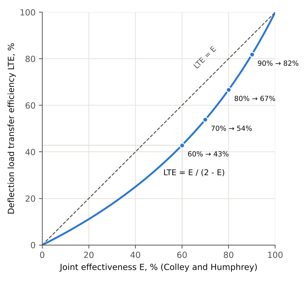
The 60% figure from the PCA tests is a joint effectiveness, E, as defined by Colley and Humphrey (5). It is often read as a deflection load transfer efficiency, LTE, which is the measure most designers and testing programs now use (6). The two are different quantities. Although the relationship between them follows directly from their definitions, it is rarely stated. Joint effectiveness compares the unloaded-side deflection with the average of the two sides, while load transfer efficiency compares the two deflections directly:
where δL and δU are the deflections of the loaded and unloaded sides of the joint. Substituting δU = LTE δL from Equation 2 into Equation 1 and cancelling δL gives E = 2LTE / (1 + LTE), which rearranges to
Both measures equal 100% for a perfect joint and 0% for a free edge, but they diverge in between (Figure 1). Joint effectiveness of 90%, 80%, 70%, and 60% corresponds to load transfer efficiency of 82%, 67%, 54%, and 43%. The 60% figures were in PCA's guidance well before ACI 360R-10: the 1983 edition of Concrete Floors on Ground reports them and calls 50% joint effectiveness through one million load cycles "an acceptable percentage limit" (18), which is about 33% LTE. The PCA finding that joint effectiveness falls to 60% at openings of 0.025 to 0.035 in. (0.64 to 0.89 mm) therefore means that load transfer efficiency has fallen to about 43% at those openings. Equation 3 relates two deflection-based measures and is exact. Stress-based load transfer efficiency is a separate quantity, related to deflection-based efficiency nonlinearly through the slab and support properties (7). Although the derivation takes four lines, the author has not found it in the literature; it was first shared informally by the author and is included here so that it can be checked and cited.
The 60% figure also understates the problem in a second way. Colley and Humphrey's results are reported as joint effectiveness against load repetitions for fixed openings. Re-plotted as load transfer efficiency against opening, with repetitions as the parameter, the same data show load transfer efficiency falling below 90%, the common minimum target for new pavement design with engineered load transfer devices, at an opening of only about 0.015 in. (0.38 mm) once repetitions accumulate, for both the 7 and 9 in. (180 and 230 mm) slabs tested. Repetitions matter as much as opening, and 2 in. (50 mm) of additional thickness did not change the outcome. The Federal Highway Administration's current guidance makes the same point for pavements: aggregate interlock "and shear capacity decreases rapidly as joint width increases above 0.03 inches" (17). For scale, a typical concrete with 400 microstrain of drying shrinkage and 15 ft (4.6 m) joint spacing produces 15 ft × 12 in./ft × 0.000400 = 0.072 in. (1.8 mm) of opening if each joint takes its share. Load transfer efficiency is also not the whole story; deflection across the joint matters too (6), and ACI 360R-10 sets joint stability limits of 0.010 in. (0.25 mm) of differential deflection for small hard wheels and 0.020 in. (0.51 mm) for cushioned tires.
The Park and Paulay Solution and Its Replication
Park and Paulay (2) consider a symmetrically reinforced member free of external restraint, in which shrinkage of the concrete is resisted only by the embedded steel. With Ac and As the concrete and steel areas, Ec and Es their moduli, Ct a creep coefficient applied through an effective concrete modulus, and εsh the free shrinkage strain, equilibrium and compatibility of a single uncracked section give the concrete tension and steel compression
with the shared shortening strain x = fs / Es. Park and Paulay note that applying a compressive creep coefficient to sustained, increasing, mainly tensile stress makes the result an approximation.
Equations 4 and 5 were coded in a self-contained calculator using the inputs listed in the guide: Es = 29,000,000 psi (200 GPa), Ec = 2,900,000 psi (20.0 GPa), Ct = 2.0, and εsh = 0.000500. Every row of the table is reproduced to the printed precision when the gross section is used, so that Ac / As = 1/ρ (Table 1). The 3.0% row is Park and Paulay's Example 10.11. The modulus of 2,900,000 psi (20.0 GPa) corresponds to a compressive strength of only about 2,600 psi (18 MPa) by the ACI 318 expression (8). The SI equivalent of Es is printed in the guide as 2,000,000 MPa; the correct value is 200,000 MPa.
Table 1. Selected Rows of ACI 360R-10 Table 6.2 Recomputed From Equation 4
| Steel ratio, % | Concrete stress, psi (tension) | Steel stress, psi (compression) | Restrained strain | Reduction in free shrinkage, % |
|---|---|---|---|---|
| 0.1 | 14 | 14,078 | 0.000485 | 2.91 |
| 0.5 | 63 | 12,609 | 0.000435 | 13.04 |
| 1.0 | 112 | 11,154 | 0.000385 | 23.08 |
| 3.0 | 229 | 7,632 | 0.000263 | 47.37 |
The Slab-on-ground Problem
Assumptions That Do Not Hold at a Sawcut Joint
Park and Paulay are explicit about the scope of their solution: its purpose is to estimate the concrete tensile stress so that it can be compared with the tensile strength, and the section is assumed to remain uncracked. A sawcut is placed so that the section will crack. Once it does, the concrete carries no tension across the crack, and the bar carries whatever force passes from one panel to the next over a short transfer length on each side. With continuous steel, Equation 4 is a reasonable description of the uncracked concrete between joints. It does not describe the joints, which is where the question of restraint is decided.
The member in Equation 4 also has no external restraint. A slab-on-ground is restrained by base friction, and each panel is coupled to its neighbors through the joints. Whether reinforcement restrains joints from opening is a question about that coupling, and a member with no neighbors and no base cannot represent it.
Strain Reduction Versus Force Transfer
For the jointing decision, the relevant quantity is the force the bars can transmit across a cracked joint compared with the force needed to crack the concrete:
where fy is the bar yield strength and ft the direct tensile strength of the concrete. This criterion is the basis of minimum longitudinal steel in continuously reinforced concrete (9). With fy = 60 ksi and ft = 300 psi (2.1 MPa), the ratio is 0.2 at 0.1% steel, 1.0 at 0.5%, and 2.0 at 1.0% (Figure 2); for ft between 250 and 350 psi (1.7 and 2.4 MPa), unity falls between about 0.4% and 0.6%. Below unity the bar yields before it can crack intact concrete elsewhere. Above unity it can crack the slab between joints, which is how continuously reinforced slabs develop closely spaced fine cracks. The guide recognizes this transition in its 0.5% minimum for eliminating sawcut joints, and Walker and Holland (3) describe the band between 0.1% and 0.5% as one to avoid. Table 6.2 passes smoothly through that band and gives no indication of it. The force criterion also explains why a lower boundary should exist. Sawcut joints activate at early age, when the direct tensile strength may be on the order of 150 psi (1.0 MPa), which brings the threshold down toward 0.25% for Grade 60 steel. A boundary at 0.1% has no basis in the table, but a force criterion evaluated at the age of joint activation can locate one.
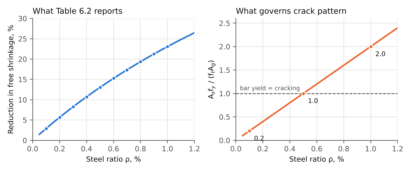
The force view also exposes a variable the table cannot see. Equation 4 contains no yield strength, so Table 6.2 gives the same result for any bar grade. The tie capacity, however, is proportional to ρfy. At 0.1%, Grade 80 bars carry the same force as Grade 60 bars at 0.133%, which lies inside the band Walker and Holland (3) recommend avoiding. If the 0.1% limit is a limit on restraint, it is properly a limit on ρfy, and it corresponds to about 0.075% for Grade 80.
Bar Tie Capacity Compared With Base Friction
The guide concludes that the strain reduction at 0.1% steel is minor compared with friction and curling, but it does not compute either on a common basis. Table 2 makes that comparison in force terms for a 6 in. (150 mm) slab weighing 75 psf (3.6 kPa). The tie capacity per foot of width is ρAgfy; the friction drag per foot of slab length is μw, with w the slab weight per unit area. Their quotient is the length of slab whose friction the bars can resist. Friction coefficients of 0.8 and 1.6 correspond approximately to first movement on polyethylene and on a granular subbase in the guide's Fig. 14.3; the values for subsequent movement are lower, about 0.5 and 0.8, which would make the steel relatively more significant still.
Table 2. Length of 6 in. (150 mm) Slab Whose Base Friction Equals the Yield Force of Grade 60 Bars
| Steel ratio, % | Tie capacity, lb/ft | μ = 0.8: ft (15 ft panels) | μ = 1.6: ft (15 ft panels) |
|---|---|---|---|
| 0.1 | 4,320 | 72 (4.8) | 36 (2.4) |
| 0.2 | 8,640 | 144 (9.6) | 72 (4.8) |
| 0.3 | 12,960 | 216 (14.4) | 108 (7.2) |
| 0.5 | 21,600 | 360 (24.0) | 180 (12.0) |
At 0.1% the bars can hold back the friction of 2.4 to 4.8 panels. As a stress over the gross section, the tie capacity is 60 psi (0.41 MPa), while friction at the center of a single 15 ft (4.6 m) panel is only 6 to 13 psi (0.041 to 0.090 MPa). The steel is not minor relative to friction, and the lower the friction, the larger its relative effect, which is consistent with the guide's observation that vapor retarders make dominant joints more pronounced. Curling stresses, which the guide places at 200 to 450 psi (1.4 to 3.1 MPa), are larger, but they are flexural, peak at different locations and times, and do not change whether a bar transmits axial force across a joint.
Shrinkage Must Go Somewhere
The table shows that 0.1% steel leaves about 97% of free shrinkage to be accommodated, and in a jointed slab that movement appears as joint opening. For εsh = 500 microstrain, rigid-plastic base friction, and an effective modulus Ec / (1 + Ct), the total opening within a 120 ft (37 m) run is about 0.65 to 0.68 in. (17 to 17 mm) for μ between 1.6 and 0.8. Shared by all eight joints, each opens about 0.08 to 0.09 in. (2.0 to 2.3 mm); if fewer joints activate, each opens more (Figure 3). These values scale with the shrinkage strain, and ultimate values of 520 to 780 microstrain, the range covered by PCA's joint factor table (16), would raise them; thermal contraction is excluded. The joint opening expression used in pavement design (10), with a base-restraint factor of 0.65 to 0.8, leads to the same conclusion. This applies equally to plain sawcut joints. The question here is not whether the total movement is large, but how the tied detail redistributes it.
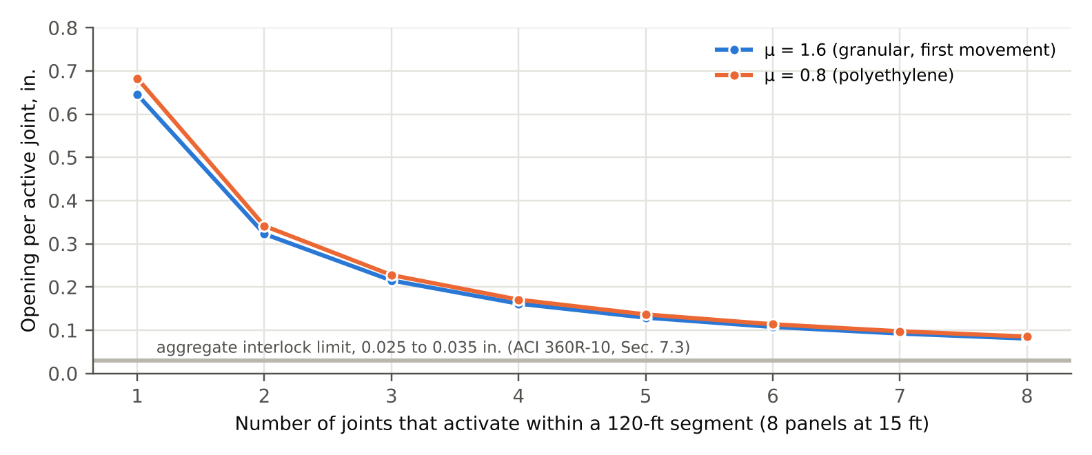
The bars can keep tied joints within the interlock range only by holding those cracks closed, that is, by carrying force. That force is the restraint the table is used to dismiss. The Gergely and Lutz expression (11), developed for flexural cracks and used here only for scale, gives about 0.03 in. (0.76 mm) for a No. 3 bar at 18 in. (460 mm) with 2 in. (50 mm) cover at 60 ksi, and a bond-slip estimate for a single crack in direct tension using the mean bond stress of fib Model Code 2010 (12) gives 0.02 to 0.03 in. (0.51 to 0.76 mm). A 0.1% bar therefore approaches yield at about the opening where interlock is lost, and once it yields it provides no further width control. Any assumption that bar stress at a tied joint is low holds only where the force reaching that joint is low, which depends on its position in the run.
The Unsymmetric Solution Matches the Recommended Detail
The table is computed for steel at mid-height. The guide, however, places the bars "above mid-depth but low enough that the sawcut will not cut the reinforcement," which in practice puts them as high as the sawcut allows, and the guide's Chapter 14 adds that upper-half steel is used so "that the steel restrains concrete shrinkage." The pages of Park and Paulay that the guide cites (457 to 461) contain, immediately after the symmetric solution, a general method for unsymmetrical reinforcement (their Eqs. 10.44 to 10.46 and Example 10.12). The free shrinkage is imposed with a fictitious force P = AstEsεsh holding the steel at the same strain, which is then released as an eccentric tension on the creep-adjusted transformed section:
where A and I are the transformed area and moment of inertia, es the eccentricity of the steel, and y the distance of the fiber from the centroid. Because the recommended detail places the steel off center, this is the solution that corresponds to it, and it is the one a design guide should present for that detail. Table 3 applies it to a 6 in. (150 mm) slab with bars 2 in. (50 mm) below the top. The top-fiber tension and the restraint of top-surface shrinkage are about twice the mid-depth values, and the bottom fiber is essentially unstressed because the steel sits near the upper kern point. The values remain small at 0.1%, and like the table they describe an uncracked member with no external restraint; the point is one of consistency.
Table 3. Shrinkage Restraint in a 6 in. (150 mm) Slab With Steel 2 in. (50 mm) Below the Top (Park and Paulay Unsymmetric Solution) Compared With Steel at Mid-Height
| Steel ratio, % | Top fiber tension, psi | Reduction at top surface, % | Mid-height tension, psi (Table 6.2) | Mid-height reduction, % (Table 6.2) |
|---|---|---|---|---|
| 0.1 | 28 | 5.8 | 14 | 2.9 |
| 0.2 | 54 | 11.1 | 27 | 5.7 |
| 0.3 | 78 | 16.1 | 40 | 8.3 |
| 0.5 | 122 | 25.1 | 63 | 13.0 |
| 1.0 | 209 | 43.3 | 112 | 23.1 |
The creep coefficient of 2.0 is a long-term value for sustained compression, whereas joints activate at early age. At 0.1% the result is insensitive to it (14 psi for Ct from 0 to 2.0), which confirms that the table carries little information at the ratio where it is used. At 0.5%, the long-term coefficient raises the computed reduction from 4.8% (elastic) to 13.0%.
A First-pass Run-level Check
Friction Demand Along a Tied Run
The behavior can be illustrated with a simple model of one run of panels between construction joints. A 120 ft (37 m) run with tied sawcut joints at 15 ft (4.6 m) is used, close to the 125 ft (38 m) maximum of ACI 360R-10. Base friction is rigid-plastic. If the construction joints open freely, the axial force in the slab at distance x from the nearer construction joint is
with a maximum of μwL/2 at mid-run. A cracked tied joint can remain tight only while N(x) is below the bar yield force ρAgfy, so the longest run in which every tied joint can hold is
For 0.1% Grade 60 steel in a 6 in. (150 mm) slab, Lmax is 144 ft (44 m) at μ = 0.8 and 72 ft (0.24 and 22 m) at μ = 1.6 (Figure 4). On polyethylene the demand stays below the tie capacity throughout the run, so tied joints that crack can hold, and nearly all of the run's shortening is delivered to the construction joints. On a granular base at first movement, the demand exceeds the tie capacity at the three central joints, which would yield and open, and the pattern then redistributes.
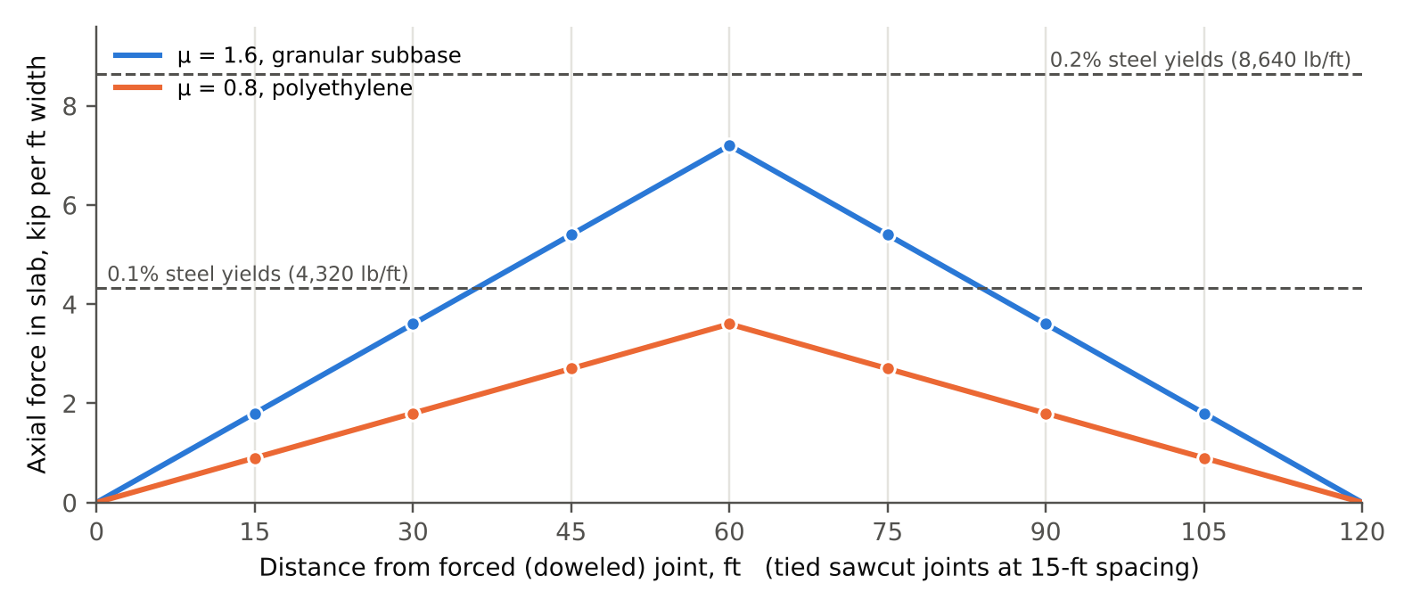
Figure 5 compares idealized openings for a run on polyethylene. With plain sawcuts that all activate, each joint opens about 0.09 in. (2.3 mm). With 0.1% steel and the tied joints holding, the tied cracks open only by bar strain and slip, estimated at 0.006 to 0.025 in. (0.15 to 0.64 mm) by scaling the Gergely and Lutz value linearly with bar stress, which overstates the width at low stress. The construction joints receive the rest, about 0.58 in. (15 mm) each when adjacent bays behave alike.
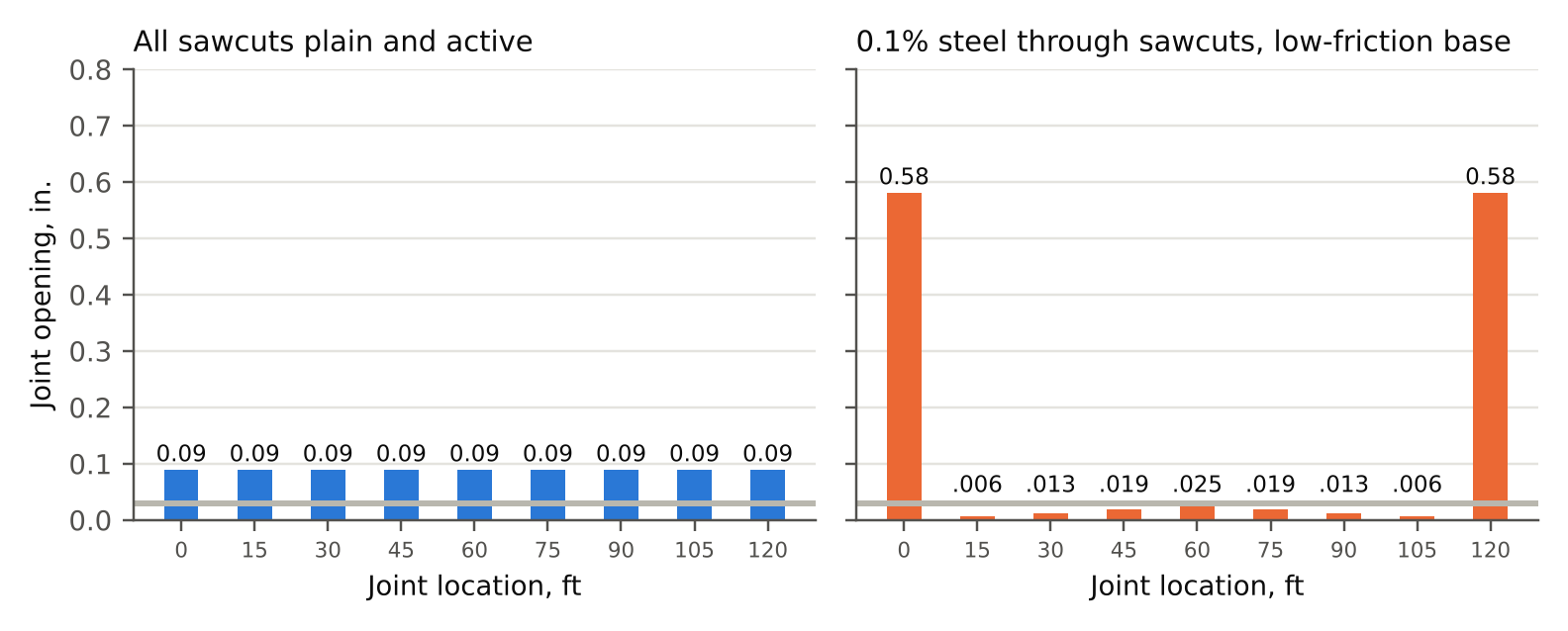
This is consistent with the guide's own description: a doweled joint is required to force activation where tied joints do not activate, wide dominant joints develop, and a vapor retarder makes them worse. The guide's Chapter 14 describes the same mechanism for slabs tied to walls, noting that the first joint from an anchored wall "tends to open much wider because all of the shrinkage from the restrained panel occurs at this joint." Tying the sawcuts can make them look stable, but the dominant joints have not been removed. They have been relocated to the doweled joints. Likewise, the statement that up to 0.1% steel "allows joints to activate" (3) needs qualification. On a low-friction base, the check suggests that the sawcut joints crack but stay nearly closed, so most of the shrinkage is not accommodated at them. A run whose tied joints hold is, in effect, a 120 ft (37 m) slab without functioning contraction joints and with one-fifth of the 0.5% steel the guide recommends for eliminating them.
Partially Reinforced Construction Joints
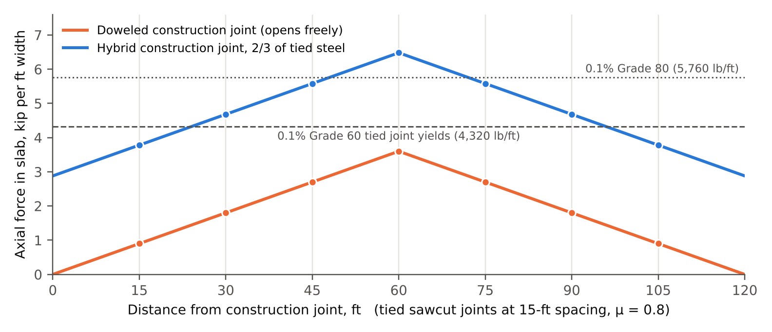
One response to wide doweled joints is a "hybrid" construction joint that carries part of the contraction joint reinforcement across it, together with dowels, to reduce its opening. Two-thirds of the contraction joint reinforcement is used here for illustration. The run-level check shows what that implies. If the hybrid joint holds, the run simply extends to the next joint that releases, and the friction accumulated before release is larger still. If it opens, its bars must be at or near yield, so it transmits a force Tcj to the slab on each side, and the demand in the run becomes
With Tcj two-thirds of the tied-joint capacity, a tied joint can hold only within x < (ρAgfy - Tcj) / (μw), which is 24 ft (7.3 m) on polyethylene and 12 ft (3.7 m) on a granular base. In a 120 ft (37 m) run on polyethylene, the five central sawcut joints now reach yield (Figure 6). The hybrid joint does not remove movement from the run. It shifts part of it back to the central sawcut joints, where the bars have yielded and no longer control width. Dowel restraint at the hybrid joint adds to Tcj and strengthens the effect. Whether the result is better or worse than a freely opening construction joint depends on the run length, friction, and joint hierarchy, which is precisely the kind of question a single-section table cannot answer and a run-level model can.
Limitations of the Rigid-Plastic Check
The check ignores curling, the time-dependent development of shrinkage and friction, temperature cycles, and the bond-slip response of bars at cracks. Measured slab-base friction builds up over a finite displacement before sliding (13), and near the center of a tied run displacements are small, so the actual demand there is lower than Equation 8 indicates; that makes it more likely, not less, that tied joints hold and movement collects at the construction joints. Treating each direction separately with the full friction coefficient is also conservative for demand, because in a slab shrinking in two directions friction opposes the resultant displacement. Lap splices are assumed to develop the bars, and the check assumes that tied sawcuts crack, which depends on early-age conditions not modeled here. It is intended to show the direction and order of magnitude of the redistribution, not to predict openings for design. That requires a run-level model that tracks restraint at every joint, friction along every panel, and the hold or shed response of each joint as shrinkage develops, such as the JOINTS tool developed by the author's company (14), together with field measurements of joint openings in slabs built with this detail.
Load Transfer Assumed in Thickness Design
ACI 360R-10 presents the detail as a way "to provide load-transfer capability without using dowels," and gives no separate thickness procedure for it, so its thickness is set by the methods of the guide's thickness chapter. Of those, the PCA and WRI methods address interior loading only, and the COE method applies a fixed joint transfer coefficient of 0.75 regardless of the joint detail. PCA, whose method the guide presents, applies a joint factor of up to 1.6 for loads at joints without load transfer in its own manual (16), but the guide's worked examples apply none. Taken together, 0.1% steel is treated as the equivalent of dowels, and a jointed slab is designed as though its joints transferred load fully.
The analysis above does not support that assumption. The only quantitative aggregate interlock data the guide cites show joint effectiveness of 60%, or load transfer efficiency of about 43%, at openings of 0.025 to 0.035 in. (0.64 to 0.89 mm). Tied joints that hold open by 0.006 to 0.025 in. (0.15 to 0.64 mm), tied joints that yield open further, and construction joints open by a substantial fraction of an inch. The bars themselves contribute little dowel action: a No. 3 bar at 18 in. (460 mm) has a small fraction of the bending stiffness of the dowels the guide recommends for joints under wheel traffic. With load transfer efficiency below 100%, stresses for loads near joints lie between the interior value and the free-edge value, so a thickness chosen for interior loading is unconservative for loads at joints. The size of the shortfall depends on the load transfer actually achieved at each joint, which in turn depends on that joint's opening.
ACI 360R-10 already acknowledges this class of problem. Its Section 14.13 notes that the PCA, WRI, and COE methods rest on Westergaard's assumption of full support (15) and give erroneous results where curled slabs lose contact with the subgrade. In each case an element-level closed-form solution, correct within its own assumptions, is used to justify a rule for a system whose behavior is decided by effects the solution excludes. Mechanistic-empirical thickness design that ties load transfer to joint opening (14) removes the assumptions of full support and full load transfer; run-level joint analysis replaces the table. For this slab type, the two are linked: the joint openings that determine load transfer are the outcome of the restraint the table describes as minor.
Recommendations
The following are suggested for design practice and for future editions of the guide:
- Do not rely on Table 6.2 to set the reinforcement limit, or relabel it as the long-term internal restraint of an uncracked, unjointed member and state that it does not predict joint activation, joint opening, or bar stress.
- Express the reinforcement limit as a tie force, ρfy, rather than a steel ratio, so that Grade 80 bars are limited to about 0.075%, and relate the limit to the ratio of tie capacity to concrete cracking force.
- Estimate bar stress at tied joints rather than assuming it is low. It is set by the force accumulated along the run and can reach yield.
- Where partial reinforcement is carried across doweled joints, base the amount on run-level analysis, recognizing that it raises the force on the adjacent tied joints.
- Require an estimate of the opening at every joint, including the doweled joints, using a method that accounts for joint restraint, base friction, and redistribution along the run, as Section 6.2 of ACI 360R-10 already calls for. Size load transfer, armoring, and joint filler at doweled joints for that opening.
- Do not present enhanced aggregate interlock as an alternative to positive load-transfer devices, and do not credit full load transfer in thickness design. Use a load transfer efficiency consistent with the estimated opening of each joint, apply an edge or joint factor, or demonstrate the joint stability limits of Section 6.2 for each joint type.
- Identify the PCA aggregate interlock results as joint effectiveness and state the corresponding load transfer efficiency, LTE = E / (2 - E).
- If a closed-form illustration is retained, use Park and Paulay's unsymmetric solution for the recommended bar position, and correct the SI value of Es.
Conclusions
The Park and Paulay solution reproduced in ACI 360R-10 Table 6.2 is arithmetically correct, but it describes an uncracked member with no joints and no base friction. It is a fair description of the concrete between joints, not of the joints themselves, and it measures strain rather than force. Restated in terms of force, 0.1% Grade 60 steel in a 6 in. (150 mm) slab can resist the base friction of several 15 ft (4.6 m) panels, Grade 80 at the same ratio enters the range industry guidance describes as one to avoid, and the bars approach yield at about the opening where aggregate interlock is lost.
The guide's own text anticipates tied joints that do not activate and dominant joints that open wide, which is what a run-level check predicts and what the table cannot. A first-pass check of a 120 ft (37 m) run on polyethylene puts the opening of the doweled joints near 0.6 in. (15 mm), and with partial reinforcement across those joints, part of that movement returns to central sawcut joints whose bars have yielded. The guide presents the detail as a substitute for dowels, and thickness design that treats such joints as fully effective is unconservative for loads near joints; the 60% joint effectiveness the guide cites corresponds to a load transfer efficiency of about 43%.
None of this means the detail is unworkable, and designers' experience with it is substantial. It means that its performance depends on how movement is distributed along the run and on the load transfer achieved at each joint. Those are questions for an analysis of the joints, not a table. Pavement engineers design joints for 90% load transfer under pneumatic tires; floors carrying small, hard lift truck wheels deserve at least the same attention.
References
1.ACI Committee 360. Guide to Design of Slabs-on-Ground. ACI 360R-10. American Concrete Institute, Farmington Hills, Mich., 2010.
2.Park, R., and T. Paulay. Reinforced Concrete Structures. John Wiley & Sons, New York, 1975, pp. 457-461.
3.Walker, W. W., and J. A. Holland. Stay Out of the Courthouse Zone. Engineering Bulletin. Structural Services, Inc., 2016.
4.Walker, W. W., and J. A. Holland. The Hidden Cost of Aggregate Interlock. Concrete Construction, Vol. 52, No. 2, 2007, pp. 36-41.
5.Colley, B. E., and H. A. Humphrey. Aggregate Interlock at Joints in Concrete Pavements. Highway Research Record 189, Highway Research Board, Washington, D.C., 1967. http://onlinepubs.trb.org/Onlinepubs/hrr/1967/189/189-001.pdf.
6.Snyder, M. B. Guide to Dowel Load Transfer Systems for Jointed Concrete Roadway Pavements. National Concrete Pavement Technology Center, Iowa State University, Ames, 2011. https://intrans.iastate.edu/app/uploads/2018/08/Dowel-load-guide.pdf.
7.Ioannides, A. M., and G. T. Korovesis. Analysis and Design of Doweled Slab-on-Grade Pavement Systems. Journal of Transportation Engineering, Vol. 118, No. 6, 1992, pp. 745-768.
8.ACI Committee 318. Building Code Requirements for Structural Concrete and Commentary. ACI 318-19. American Concrete Institute, Farmington Hills, Mich., 2019.
9.Vetter, C. P. Stresses in Reinforced Concrete Due to Volume Changes. Transactions of the American Society of Civil Engineers, Vol. 98, 1933, pp. 1039-1053.
10.American Association of State Highway and Transportation Officials. AASHTO Guide for Design of Pavement Structures. AASHTO, Washington, D.C., 1993.
11.Gergely, P., and L. A. Lutz. Maximum Crack Width in Reinforced Concrete Flexural Members. In Causes, Mechanism, and Control of Cracking in Concrete, SP-20, American Concrete Institute, Detroit, Mich., 1968, pp. 87-117.
12.International Federation for Structural Concrete (fib). fib Model Code for Concrete Structures 2010. Ernst & Sohn, Berlin, 2013.
13.Wesevich, J. W., B. F. McCullough, and N. H. Burns. Stabilized Subbase Friction Study for Concrete Pavements. Research Report 459-1. Center for Transportation Research, The University of Texas at Austin, 1987.
14.The Slab Designer, LLC. SLABS and JOINTS. https://slabs.design. Accessed October 2026.
15.Westergaard, H. M. Stresses in Concrete Pavements Computed by Theoretical Analysis. Public Roads, Vol. 7, No. 2, 1926, pp. 25-35.
16.Farny, J. A., and S. M. Tarr. Concrete Floors on Ground, 4th ed. EB075. Portland Cement Association, Skokie, Ill., 2008.
17.Federal Highway Administration. Concrete Pavement Joints. Technical Advisory T 5040.30. FHWA, Washington, D.C., January 2019, Section 7b.
18.Spears, R. E., and W. C. Panarese. Concrete Floors on Ground. EB075.02D, 2nd ed. Portland Cement Association, Skokie, Ill., 1983.
Related in This Series
- Article on this topic: A Little Steel Through the Sawcut Is Not as Harmless as the Table Says
The 0.1% limit for continuous steel through sawcuts rests on a table that answers a different question than the joints ask.
- Light Reinforcement Through Sawcut Joints: Tolerances and the JRCP Record
Thickness tolerances push as-built steel ratios past 0.1%, and the highway record of JRCP shows where that detail leads.
- Joint Load Transfer and Slab Thickness for Speculative Warehouse Floors
Mechanistic-empirical design and contractor cost survey for one spec warehouse with three joint details.
- Joint Spacing, Curling, and the Factor of Safety in ACI 360R-10
Checks the Fig. 6.6 joint spacing and the Table 5.2 factor of safety against the guide's own curling and fatigue data.
- PCA's Airport Pavement Method on Industrial Floors
Validates a rebuild of PCA's 1973 airport method and explains why its flexible inputs do not make it an industrial floor design basis.
Revision history
- November 3, 2026: Completed references; added metric units and links to other pieces in the series.
- October 30, 2026: First published on slabs.design/knowledge.
To cite this paper, use the citation printed in the PDF. It includes the revision date, so readers can match your citation to the text you read.