Technical Paper|TSD-07TP
Joint Spacing, Curling, and the Factor of Safety in ACI 360R-10: Two Assumptions the Guide's Own Data Do Not Support
The Slab Designer, LLC | Published October 28, 2026 | Revised November 4, 2026
Abstract
ACI 360R-10 presents three thickness design methods, PCA, WRI, and COE, that are based on Westergaard's solutions for a fully supported slab and check the tensile stress from load alone. Two statements in the guide allow those methods to be used for floors that curl. First, Section 4.4.7 states that by following the joint spacing of Fig. 6.6, "the curling stresses will be sufficiently low that the PCA, WRI, and COE methods will provide reasonable solutions." Second, Chapter 5 sets the factor of safety as the inverse of a stress ratio computed from load stress, with stress ratios below 0.45 permitting unlimited load repetitions. This paper tests both statements against the guide's own data and references. Using the Westergaard-Bradbury formula that the guide cites, the guide's coefficient of thermal expansion, and its recommended equivalent gradients for enclosed slabs, square panels at the Fig. 6.6 spacings for typical concrete develop 75% to 88% of the maximum curling stress coefficient on a subgrade modulus of 100 pci (27 MPa/m), and 90% to 97% on 200 pci (54 MPa/m). Halving the curling stress in a 6 in. (150 mm) slab would require joints at about 10 ft (3.0 m) rather than 14 ft (4.3 m). The resulting stresses, about 140 to 520 psi (0.97 to 3.6 MPa) for 6 and 8 in. (150 and 200 mm) slabs, match the 200 to 450 psi (1.4 to 3.1 MPa) range the guide itself reports, and the guide notes that analysis allowing lift-off gives higher values still. On the factor of safety, the thickness methods check tension at the bottom of the slab under an interior load, which upward curling relieves, while loads near the joints of a curled slab produce tension at the top, where curling stress already acts. If even 100 psi (0.69 MPa) of curling stress coincides with a load designed at a stress ratio of 0.45, the combined ratio of 0.60 corresponds to about 31,000 allowable repetitions in the guide's Table 5.3, rather than unlimited; at 200 psi (1.4 MPa), it corresponds to about 360. The paper recommends that the guide stop describing the Fig. 6.6 spacing as making curling stresses low, and that thickness design include the top-fiber stress from loads at joints combined with curling.
Keywords: slab-on-ground, curling, warping, joint spacing, factor of safety, fatigue, thickness design
Introduction
Curling is not a side topic in ACI 360R-10 (1). A simple word count of the guide finds "curl" and its variants 121 times, the 18th most frequent term in the document, and "shrinkage" 268 times, more often than "thickness" (174). The guide's authors plainly understood that curl governs much of floor performance; Walker and Holland's "First Commandment" article (4), now more than 25 years old, did much to bring the magnitude of curling stresses to the industry's attention. The question this paper asks is narrower: whether the thickness procedure the guide presents carries that understanding through to a design.
The three thickness design methods presented in the guide trace to Westergaard's solutions for a slab in full contact with a uniform foundation (2). Each computes a tensile stress from a wheel, post, or distributed load and compares it with the concrete's modulus of rupture divided by a factor of safety. None includes stress from curling. The guide is candid about this. Its Chapter 14 states that curling stresses "can easily range from 200 to 450 psi," and Section 14.13 states that because the three methods assume full support, "they give erroneous results for slab thickness where the slab is not in contact with the subgrade."
The guide reconciles these positions with two statements that, taken together, permit the methods to be used as they are. The first is that the joint spacing of Fig. 6.6 keeps curling stresses low enough that the methods remain reasonable. The second is that the factor of safety, defined on load stress, controls fatigue, with stress ratios below 0.45 permitting unlimited repetitions. This paper examines both, using only the guide's own inputs, its cited references, and closed-form solutions it presents. The purpose is not to argue that the methods should be abandoned overnight, but to show that the two statements do not hold on the guide's own terms, and to suggest what the guide should say instead. No software output is used; every result can be reproduced by hand from the guide's own numbers.
What the Guide Says
Joint Spacing and Curling
Section 4.4.7, on uniformity of support, notes that the design charts "assume continuous slab contact with the base and a uniform subgrade modulus," that "continuous intimate contact is not achieved in practice because of differences in composition, thickness, moisture content, slab curling, and subgrade density," and then: "By following the joint recommendations in Fig. 6.6, the curling stresses will be sufficiently low that the PCA, WRI, and COE methods will provide reasonable solutions." Chapter 5 makes a parallel statement for restraint stresses: "When the joint spacing recommendations given in Fig. 6.6 are followed, then these stresses will be sufficiently low."
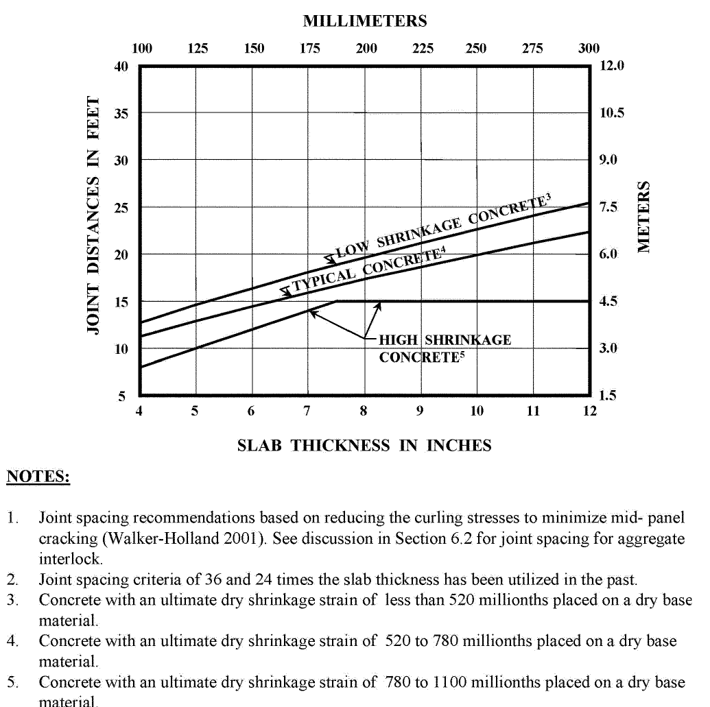
Fig. 6.6 gives joint spacing as a function of slab thickness for low-shrinkage, typical, and high-shrinkage concrete placed on a dry base. Its first note states that the "joint spacing recommendations [are] based on reducing the curling stresses to minimize mid-panel cracking," citing Walker and Holland (3). The accompanying text adds that the spacings "are based on shrinkage values for specimens that have been moist-cured 7 days and then placed in air storage." For typical concrete, the figure gives about 11 ft (3.4 m) for a 4 in. (100 mm) slab, 14 ft (4.3 m) for 6 in. (150 mm), 17 ft (5.2 m) for 8 in. (200 mm), 20 ft (6.1 m) for 10 in. (250 mm), and 22 ft (6.7 m) for 12 in. (300 mm).
Curling Stress
Chapter 14 gives the guide's quantitative treatment of curling. Section 14.1 cites Walker and Holland (4) for curling stresses of 200 to 450 psi (1.4 to 3.1 MPa). Section 14.12 states that warping stress increases with slab length only up to a critical length, measured diagonally, beyond which it does not increase, and tabulates critical lengths, for example 26 to 27 ft (7.9 to 8.2 m) for a 6 in. (150 mm) slab at gradients of 20°F to 30°F (11 to 17°C). Section 14.13 reviews the Westergaard-Bradbury formula (5) used by Kelley (6), notes that Leonards and Harr (7), with a model that allowed the slab to lift off the subgrade, calculated stresses about 29% greater than Kelley's for nearly the same case "due to their better assumptions," and recommends that enclosed slabs be designed for a negative (upward-curling) gradient of 3°F to 6°F per inch of thickness (1.7 to 3.3°C per 25 mm). Section 14.2 gives the coefficient of thermal expansion as 5.5 × 10⁻⁶ per °F. Section 14.13 also notes that "the three slab thickness design methods permit thinner slabs as the modulus of subgrade reaction increases," whereas a higher modulus "increases the length of unsupported curled slab edges" and increases curling stress.
Factor of Safety and Fatigue
Chapter 5 lists commonly used factors of safety of 1.7 to 2.0 for moving wheel and concentrated loads (Table 5.2). It states that "for stress ratios less than 0.45, concrete can be subjected to unlimited load repetitions," gives allowable repetitions for higher ratios in Table 5.3, taken from PCA (8), and states that "the factor of safety is the inverse of the stress ratio." The stress in the ratio is the load stress computed by the thickness method.
Part 1: Curling Stress at the Fig. 6.6 Spacings
Method
The Westergaard-Bradbury formula (5, 9) gives the curling stress at the edge and interior of a slab of length L in full contact with a Winkler foundation under a linear temperature difference ΔT through the thickness:
where E is the concrete modulus, α the coefficient of thermal expansion, μ Poisson's ratio, and C a coefficient that depends on L/ℓ, with ℓ the radius of relative stiffness:
The coefficient rises from zero for a very short slab to a maximum of 1.08 at L/ℓ of about 9, then settles near 1.0 for long slabs. That plateau is the critical-length behavior described in Section 14.12. A moisture gradient in an enclosed slab is represented here, as in the guide, by an equivalent temperature gradient.
Inputs follow the guide: α = 5.5 × 10⁻⁶ per °F (Section 14.2), E = 3,000,000 psi (as used for the Section 14.12 critical lengths) and 4,000,000 psi (27.6 GPa), μ = 0.15, k = 100 and 200 pci (27 and 54 MPa/m), and equivalent negative gradients of 3°F (1.7°C), 5°F (2.8°C), and 6°F per inch (Section 14.13). Panels are square at the Fig. 6.6 spacing for typical concrete.
Results
Table 1 shows the coefficient C at the Fig. 6.6 spacings. On a subgrade modulus of 100 pci (27 MPa/m), the panels develop 75% to 88% of the maximum coefficient; on 200 pci (54 MPa/m), 90% to 97%. Thinner slabs sit closer to the maximum. The Fig. 6.6 spacings therefore do not place slabs in a low-curling range of the Westergaard-Bradbury curve; they place them on its upper shoulder (Figure 2). This agrees with Section 14.12: the diagonal of a 14 ft (4.3 m) square panel is about 20 ft (6.1 m), three-quarters of the 26 to 27 ft (7.9 to 8.2 m) critical length the guide gives for a 6 in. (150 mm) slab.
Table 1. Curling Stress Coefficient at ACI 360R-10 Fig. 6.6 Spacings for Typical Concrete (E = 4,000,000 psi)
| Slab, in. | Fig. 6.6 spacing, ft | ℓ at k = 100, in. | C at k = 100 | % of max | ℓ at k = 200, in. | C at k = 200 | % of max |
|---|---|---|---|---|---|---|---|
| 4 | 11.3 | 21.6 | 0.95 | 88 | 18.2 | 1.06 | 97 |
| 6 | 14.1 | 29.3 | 0.88 | 81 | 24.6 | 1.02 | 94 |
| 8 | 16.9 | 36.4 | 0.84 | 77 | 30.6 | 0.99 | 92 |
| 10 | 19.6 | 43.0 | 0.82 | 76 | 36.1 | 0.98 | 91 |
| 12 | 22.4 | 49.3 | 0.82 | 75 | 41.4 | 0.98 | 90 |
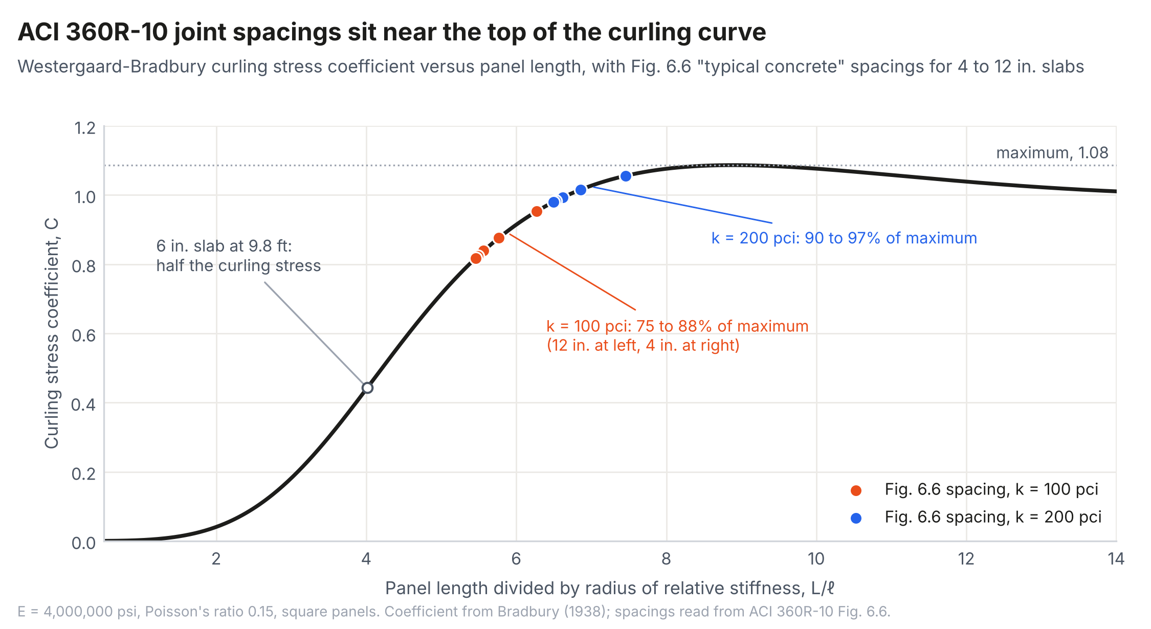
Table 2 gives the resulting stresses for 6 and 8 in. (150 and 200 mm) slabs on k = 100 pci (27 MPa/m). Across the guide's recommended gradients and the two moduli, the edge stress is about 140 to 440 psi (0.97 to 3.0 MPa) and the interior stress about 165 to 520 psi (1.1 to 3.6 MPa). These bracket the 200 to 450 psi (1.4 to 3.1 MPa) the guide reports in Section 14.1. Because Equations 1 and 2 assume full contact, and the guide itself reports that an analysis permitting lift-off gave stresses about 29% higher than the Westergaard-Bradbury result for nearly the same case, the values in Table 2 should be read as lower estimates for upward-curled slabs.
Table 2. Westergaard-Bradbury Curling Stress, psi, at Fig. 6.6 Spacing (k = 100 pci [27 MPa/m])
| Slab, in. | E, psi | 3°F/in. edge | 3°F/in. interior | 5°F/in. edge | 5°F/in. interior | 6°F/in. edge | 6°F/in. interior |
|---|---|---|---|---|---|---|---|
| 6 | 3,000,000 | 140 | 165 | 233 | 275 | 280 | 329 |
| 6 | 4,000,000 | 173 | 204 | 289 | 340 | 347 | 408 |
| 8 | 3,000,000 | 180 | 212 | 301 | 354 | 361 | 425 |
| 8 | 4,000,000 | 221 | 260 | 369 | 434 | 443 | 521 |
The same equations show what spacing would actually make curling stresses low. For the 6 in. (150 mm) slab on k = 100 pci (27 MPa/m) with E = 4,000,000 psi (27.6 GPa), halving the coefficient requires a spacing of about 9.8 ft (3.0 m) rather than 14.1 ft (4.3 m); for the 8 in. (200 mm) slab, about 11.9 ft (3.6 m) rather than 16.9 ft (5.2 m). Because C falls steeply below L/ℓ of about 6, modest reductions in spacing below Fig. 6.6 values produce large reductions in curling stress, but the Fig. 6.6 values themselves are not in that range.
Interpretation
Note 1 of Fig. 6.6 describes the spacings as reducing curling stresses "to minimize mid-panel cracking." Read with Section 4.4.7, the intent is that at these spacings curl and warp stresses are reduced enough to be of lesser concern in design for loads. Table 1 shows that they are not: the Fig. 6.6 spacings leave most of the curling stress in place. If joint spacing were the lever chosen to manage curl, the spacings would have to be considerably shorter. That short-panel approach exists; it is the basis of the OptiPave design method of TCPavements and has been applied to interior slabs internationally and in the United States, although the overall direction of slab-on-ground practice has been toward fewer joints and longer spacing. The consequence of the curling stress the Fig. 6.6 spacings leave in place is the subject of Part 2.
Table 1 also illustrates the anomaly described in Section 14.13 (see also TSD-06TP in this series, on the modulus of subgrade reaction). Doubling the subgrade modulus from 100 to 200 pci (27 to 54 MPa/m) moves every Fig. 6.6 panel closer to the maximum coefficient, raising curling stress by roughly 10% to 20%, while the thickness charts reduce the required thickness for the higher modulus. A designer who adds subbase to raise k, as Fig. 4.6 of the guide permits, can therefore thin the slab and increase its curling stress at the same time.
Part 2: What the Factor of Safety Measures
The Fiber That Is Checked
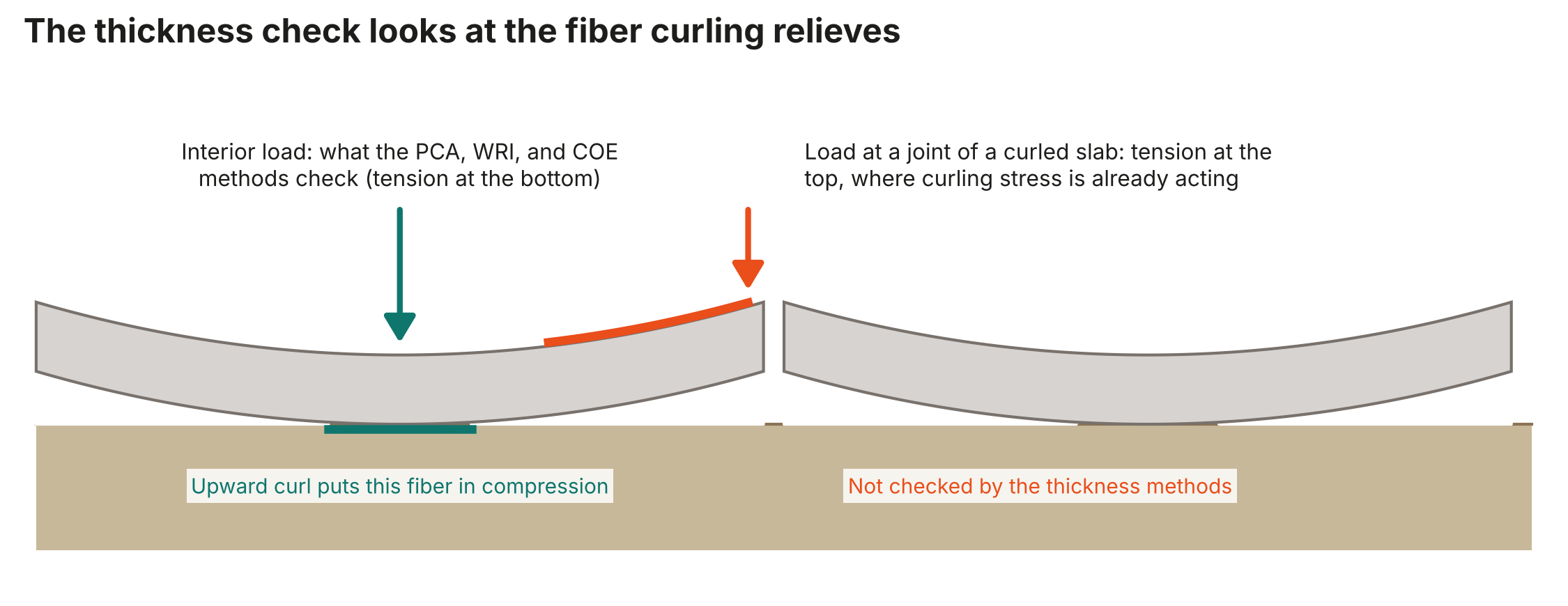
The PCA, WRI, and COE methods compute the tensile stress at the bottom of the slab under a load in the panel interior (or, for COE, at a joint with a fixed transfer coefficient), and the factor of safety is applied to that stress. Indoor slabs curl upward, because the top dries and shrinks more than the bottom. Upward curling places the top of the slab in tension and, in the region of full contact, the bottom in compression. At the location the thickness methods check, curling therefore reduces the governing stress rather than adding to it.
The location where curling and load combine is near the joints. Section 14.13 describes it: where curled edges lose contact, a load near the joint is carried by the slab as a cantilever, which produces tension at the top of the slab, the same fiber that curling has already placed in tension (Figure 3). Top-down cracking parallel to joints and corner breaks, both familiar forms of floor distress, are the result. None of the three methods computes this stress.
Even with full support, the top-fiber stress from a load at a slab corner is larger than the bottom-fiber stress from the same load in the interior. For a 5,000 lb (22 kN) wheel on a 4 in. (100 mm) radius contact area on a 6 in. (150 mm) slab (E = 4,000,000 psi, k = 100 pci [27 MPa/m]), Westergaard's corner formula gives 261 psi (1.8 MPa) of top tension and his interior formula 203 psi (1.4 MPa) of bottom tension. A load stress equal to the interior design stress is therefore, if anything, an understatement of the load stress at the top fiber near a joint, before any loss of support is considered.
Combined Stress Ratio
Table 3 and Figure 4 show the stress ratio when curling stress acts on the same fiber as a load stress designed to the guide's commonly used factors of safety, for a modulus of rupture of 650 psi (4.5 MPa), with allowable repetitions from the guide's Table 5.3. The table is a sensitivity analysis rather than a prediction for a particular slab: the fraction of the curling stress that coincides with the load stress depends on load position, panel geometry, the degree of lift-off, and the timing of curling, and an analysis of a specific floor requires a model that includes them. The table shows how little coincident curling stress the factor of safety can absorb.
Table 3. Combined Stress Ratio and Allowable Repetitions (Modulus of Rupture 650 psi, ACI 360R-10 Table 5.3)
| Coincident curling stress, psi | SF 2.2 (ratio 0.45): ratio | Repetitions | SF 2.0 (ratio 0.50): ratio | Repetitions | SF 1.7 (ratio 0.59): ratio | Repetitions |
|---|---|---|---|---|---|---|
| 0 | 0.45 | 62,790,761 | 0.50 | 762,043 | 0.59 | 40,842 |
| 100 | 0.60 | 30,927 | 0.65 | 7,700 | 0.74 | 630 |
| 150 | 0.68 | 3,343 | 0.73 | 832 | 0.82 | 68 |
| 200 | 0.76 | 361 | 0.81 | 90 | 0.90 | 7 |
| 300 | 0.91 | 6 | 0.96 | 1 | 1.05 | Cracks |
| 450 | 1.14 | Cracks | 1.19 | Cracks | 1.28 | Cracks |
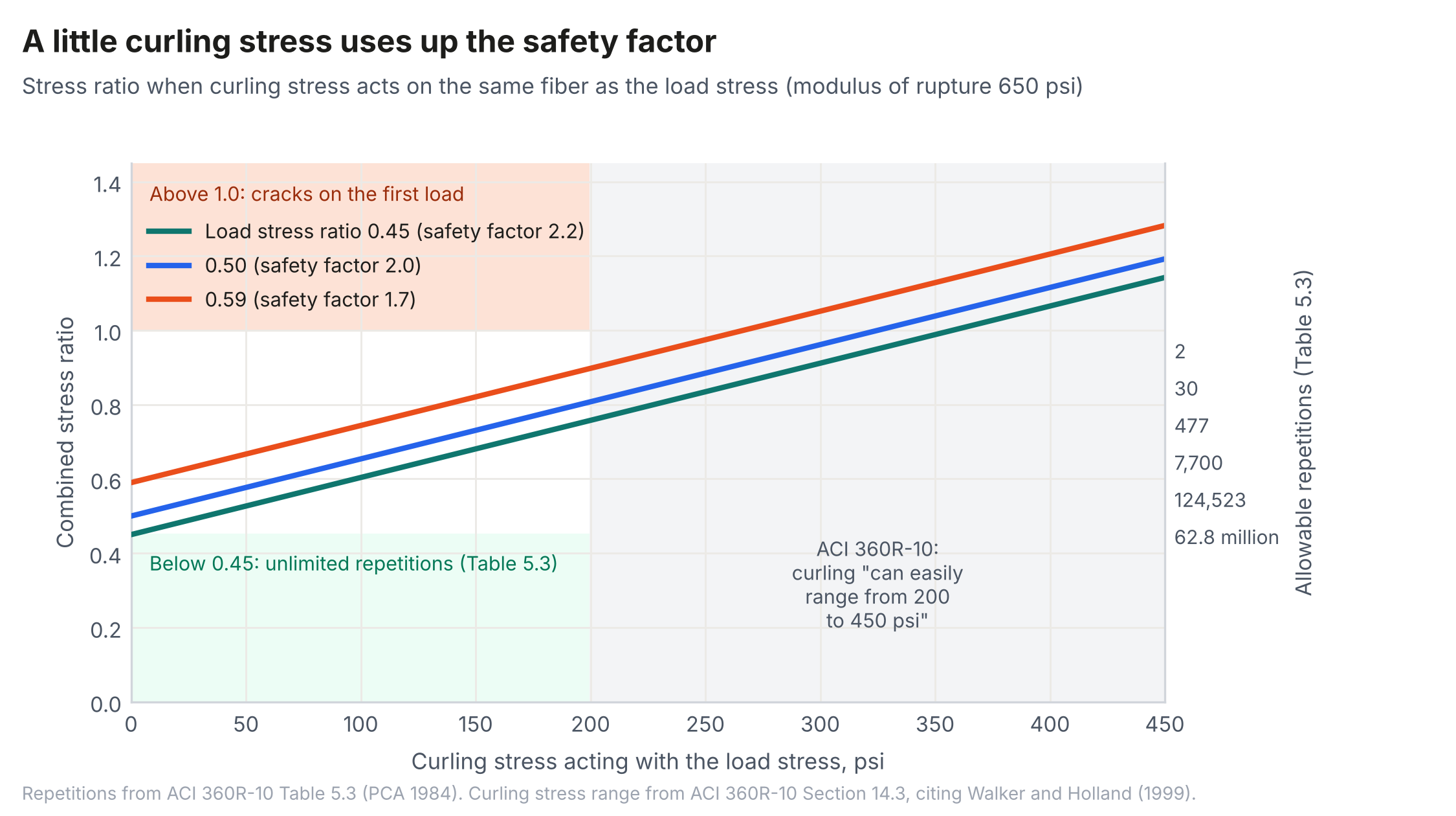
At a load stress ratio of 0.45, which the guide describes as permitting unlimited repetitions, 100 psi (0.69 MPa) of coincident curling stress reduces the allowable repetitions to about 31,000, and 200 psi (1.4 MPa), the low end of the guide's own range, reduces them to about 360. At the upper end of the guide's range, the combined stress exceeds the modulus of rupture for every factor of safety in Table 5.2. A lift truck crossing a joint several hundred times a day uses 31,000 repetitions in a few months.
Interpretation
The factor of safety in Chapter 5 is the inverse of a ratio between one stress, at one fiber, and the modulus of rupture. For an upward-curled slab, that stress is at the fiber curling relieves, and the fiber curling loads is not checked. The factor of safety therefore does not cover the stress state that governs performance near joints, and the "unlimited repetitions" associated with a stress ratio of 0.45 do not apply there. Practitioners have long compensated with conservative factors of safety; Table 3 shows why the commonly used factors are not, by themselves, enough to cover the curling stresses the guide reports.
Adding a curling stress to a load stress is itself a simplification. Under upward curl the slab loses contact with its support, and a load near a joint pushes it back down, so the contact area, the stress distribution, and the critical fiber all change with the size and position of the load. The combined stress can be above or below the simple sum, and the response is not linear in either the curl or the load. Mechanistic analysis that treats curl as an input alongside the loads, and solves the two together, is needed for a specific floor (10). Superposition is used here because it is the simplest arithmetic the guide's own tools permit. The point is that even the simplest arithmetic shows the factor of safety is not covering curling.
The capacity side of the ratio is also a simplification. The modulus of rupture is measured on a small, simply supported beam. A slab-on-ground differs from that beam in geometry, support, and stress distribution, can redistribute load, and carries more than the beam strength suggests. Table 3, like the guide, compares slab stresses with the beam strength. Taken at face value, it predicts cracking in many floors that have performed well. Both sides of the ratio have to be right before the equations can begin to explain the performance record of slabs-on-ground: the demand, with curl and load solved together, and the slab's capacity, converted from the beam strength. SLABS does the latter with a thickness-dependent geometry factor and a separate factor for fibers (11). Without that conversion, an analysis that accounts for curl correctly would still be compared with the wrong strength.
Discussion
The two statements examined here support each other in the guide's logic. If the Fig. 6.6 spacing made curling stress small, a factor of safety on load stress would be reasonable; and if the factor of safety covered curling, the joint spacing would not need to do so. Neither holds on the guide's own data. The Fig. 6.6 spacings leave slabs with most of the curling stress they would have at any length, and that stress, at the guide's own magnitudes, consumes most or all of the factor of safety at the fiber where it acts.
None of this is new information, and none of it requires new research. Every input used here is in the guide: its curling stress range, its critical lengths, its gradients, its coefficient of thermal expansion, its cited formulas, its acknowledgment of lift-off effects, its factors of safety, and its fatigue table. The issue is that the statements in Sections 4.4.7 and Chapter 5 are not reconciled with Chapter 14.
The consequences are practical. A designer, reviewer, or expert witness reading Section 4.4.7 may reasonably conclude that a slab designed by one of the three methods, with joints per Fig. 6.6, has accounted for curling. The analysis above shows that it has not, and the guide's own Section 14.13 says as much.
Recommendations
- Revise Section 4.4.7 so that it does not state that the Fig. 6.6 spacing makes curling stresses low. State instead that the spacings are intended to limit mid-panel cracking, that curling stresses at these spacings remain substantial, and that substantially shorter spacing would be needed if joint spacing were the means of reducing curl.
- Require a check of top-fiber tension near joints for loads at joints of curled slabs, with curl for a stated gradient analyzed together with the load, in addition to the interior-load check. Superposition of separately computed stresses may serve as a screening estimate only.
- Define the stress ratio for fatigue on the combined stress at the critical fiber, or, as an interim measure, deduct an estimate of curling stress from the modulus of rupture before applying the factor of safety.
- Present the relationship between joint spacing, radius of relative stiffness, and curling stress (Equations 1 to 3) so that designers can see the effect of shorter spacing, thicker slabs, and stiffer support on curling.
- Recognize in the thickness chapter, not only in Chapter 14, that increasing the subgrade modulus increases curling stress, so that subbase credit used to reduce thickness is weighed against it.
- Base the allowable stress on the capacity of a slab-on-ground rather than the modulus of rupture of the test beam, with a stated conversion, so that a stress computed with curl and loss of support is compared with a consistent strength.
- Encourage mechanistic analysis, which the guide already notes is appropriate for slabs with discontinuities, that includes curling, loss of support, and load transfer at joints, with curl characterized from field measurement where possible, for example as an effective built-in temperature difference derived from floor profile data (10).
Conclusions
ACI 360R-10 permits interior-load thickness methods to be used for slabs that curl on the basis of two statements: that Fig. 6.6 joint spacing makes curling stress low, and that a factor of safety on load stress governs fatigue. Using the guide's own inputs, Fig. 6.6 spacings for typical concrete develop 75% to 97% of the maximum Westergaard-Bradbury curling stress coefficient, depending on subgrade modulus, and stresses that match the 200 to 450 psi (1.4 to 3.1 MPa) range the guide reports, which it notes are understated by analyses that ignore lift-off. The thickness methods check the fiber that upward curling relieves; at the fiber curling loads, near joints, as little as 100 psi (0.69 MPa) of coincident curling stress reduces the allowable repetitions at a stress ratio of 0.45 from unlimited to about 31,000. The guide already contains every number needed to see this. What it lacks is a statement that reconciles its thickness chapter with its curling chapter, and a design check at the location where the two meet.
References
1.ACI Committee 360. Guide to Design of Slabs-on-Ground. ACI 360R-10. American Concrete Institute, Farmington Hills, Mich., 2010.
2.Westergaard, H. M. Stresses in Concrete Pavements Computed by Theoretical Analysis. Public Roads, Vol. 7, No. 2, 1926, pp. 25-35.
3.Walker, W. W., and J. A. Holland. Design of Unreinforced Slabs-on-Ground Made Easy. Concrete International, Vol. 23, No. 5, 2001, pp. 37-42.
4.Walker, W. W., and J. A. Holland. The First Commandment for Floor Slabs: Thou Shalt Not Curl Nor Crack... (Hopefully). Concrete International, Vol. 21, No. 1, 1999, pp. 47-53.
5.Bradbury, R. D. Reinforced Concrete Pavements. Wire Reinforcement Institute, Washington, D.C., 1938.
6.Kelley, E. F. Applications of the Results of Research to the Structural Design of Concrete Pavement. ACI Journal, Proceedings Vol. 35, No. 6, 1939, pp. 437-464.
7.Leonards, G. A., and M. E. Harr. Analysis of Concrete Slabs-on-Ground. Proceedings, ASCE, Vol. 85, SM3, 1959, pp. 35-58.
8.Portland Cement Association. Thickness Design for Concrete Highway and Street Pavements. EB109.01P. Portland Cement Association, Skokie, Ill., 1984.
9.Westergaard, H. M. Analysis of Stresses in Concrete Roads Caused by Variations of Temperature. Public Roads, Vol. 8, No. 3, 1927, pp. 54-60.
10.Face, A., and N. Parkes. Addressing Concrete Slab Curl Numbers. ForConstructionPros, 2026.
11.Covarrubias, J. P., R. Rodden, L. Khazanovich, J. Roesler, and N. Parkes. Mechanistic-Empirical Design of Concrete Slabs-on-Ground. Concrete International, American Concrete Institute, July 2026.
Related in This Series
- Article on this topic: Two Promises in the Floor Design Guide That Curling Breaks
The guide says its joint spacing keeps curl low and its factor of safety covers the rest. Its own numbers say otherwise.
- The Modulus of Subgrade Reaction for Slabs-on-Ground
Compares CBR-to-k correlations with a calibrated elastic layered method and evaluates the SSI long-term k-value approach.
- Joint Load Transfer and Slab Thickness for Speculative Warehouse Floors
Mechanistic-empirical design and contractor cost survey for one spec warehouse with three joint details.
- The Thickness Methods of ACI 360R-10 and Their PCA Lineage
Traces how PCA added a joint factor in 2001 and 2008 that ACI 360R-10's thickness procedure still omits.
- Reinforcement Continued Through Sawcut Contraction Joints
Shows the section-level solution behind the 0.1% limit does not address force transfer across a joint or redistribution of opening.
Revision history
- November 4, 2026: Added ACI's recommended joint spacing chart; noted short-panel use in the United States; added metric units to k-values.
- November 3, 2026: Completed references; added metric units and links to other pieces in the series.
- October 28, 2026: First published on slabs.design/knowledge.
To cite this paper, use the citation printed in the PDF. It includes the revision date, so readers can match your citation to the text you read.