Technical Paper|TSD-08TP
Joint Load Transfer and Slab Thickness for Speculative Warehouse Floors: Undoweled, Doweled, and Lightly Reinforced Joints
Nigel Parkes and Robert Rodden (The Slab Designer, LLC); Juan Pablo Covarrubias (TCPavements-FORTA)
The Slab Designer, LLC | Published October 29, 2026 | Revised November 8, 2026
Abstract
Floors in speculative (spec) industrial buildings are designed before a tenant is known, most often by reference to ACI 360R-10, which directs thickness design to the 2001 edition of the Portland Cement Association (PCA) publication Concrete Floors on Ground. In practice, the joint detail is often chosen after thickness is fixed, among undoweled sawcut joints, dowels at all joints, or 0.1% deformed reinforcement through the sawcuts (enhanced aggregate interlock), as though it did not affect capacity. This paper traces how the PCA method moved from interior-load charts to joint factors for vehicle and post loads in 2001, and to free-edge charts for vehicles with joint factors tied to shrinkage in 2008, an edition ACI 360R-10 did not incorporate. It shows that the aggregate interlock data cited by ACI 360R-10 are reported as joint effectiveness, and that 60% joint effectiveness corresponds to about 43% deflection load transfer efficiency (LTE). A mechanistic-empirical design of one 172,800 sq ft (16,050 m²) warehouse, using a tool built on the same ISLAB2000 lineage used in later PCA work, gives minimum thicknesses of 10 in. (250 mm) undoweled (LTE below 4%), 9.5 in. (240 mm) with 0.1% steel (LTE 37%), and 7 in. (180 mm) doweled (LTE 90%). A contractor relative cost survey places the doweled and 0.1% steel designs at 82% and 92% of the undoweled cost. The three designs have the same joint length, but stable doweled joints reduce long-term maintenance. Doweled and lightly reinforced slabs should not be assigned the same thickness, and 0.1% steel performs mechanically closer to an undoweled slab.
Keywords: slab-on-ground, speculative warehouse, joint load transfer, dowels, aggregate interlock, slab thickness design, relative cost
Introduction
A speculative, or spec, industrial building is designed and built before its tenant is known. The developer designs the floor for a plausible range of rack and lift truck loads and competes on first cost. In that market, the floor discussion usually narrows to three joint details at a common joint spacing: undoweled sawcut contraction joints with dowels only at construction joints; dowels at all joints; or a continuous 0.1% layer of deformed reinforcement through the sawcuts, described in ACI 360R-10 as enhanced aggregate interlock (1).
These options are frequently priced as alternates on a slab of fixed thickness. That practice assumes the joint detail affects serviceability but not capacity. Load transfer at joints, however, governs the stress produced by loads at or near joints, and therefore the thickness required to carry them. This paper examines that assumption from three directions: the history of the thickness design method most often used for spec buildings in the United States, the way aggregate interlock performance is reported in ACI 360R-10, and a mechanistic-empirical design and contractor cost comparison of the three options for a single warehouse.
Background
Design Practice for Spec Buildings
Engineers designing spec building floors commonly reference ACI 360R-10, Guide to Design of Slabs-on-Ground (1). It is a guide, not a code: it presents methods and experience and leaves their selection and application to the designer. Of the thickness design methods it describes, the PCA method is the one most often used for spec buildings in the United States. For that method, ACI 360R-10 refers designers to the 2001 edition of PCA's Concrete Floors on Ground (2). A spec floor designed "per ACI 360R-10" is therefore, for thickness, designed to PCA 2001.
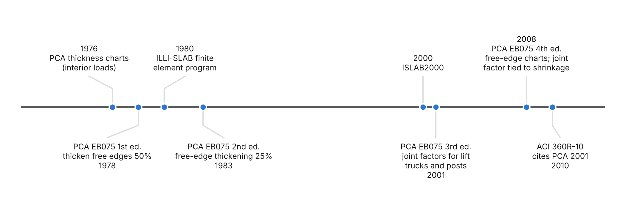
Evolution of the PCA Method
The PCA thickness charts in use through the 1990s, developed by Packard (3), were based on a load at the interior of a panel, away from joints and edges. An interior load is the most favorable location. A load at a joint without effective load transfer is carried largely by the edge of one panel and produces substantially higher flexural stress.
The 2001 third edition of Concrete Floors on Ground (2) began to address this gap by introducing joint factors for vehicle and rack post loads, so that loads near joints without effective load transfer require a thicker slab than the same loads at the interior. The 2008 fourth edition, by Farny and Tarr (4), refined the approach for vehicle loads. It states that the thickness charts of previous editions "assumed infinite slab dimensions (no joints)," a condition that "only exists where complete load transfer is achieved at the joints," and that they "are not sufficient to compute the required slab thickness where load-transfer is not accounted for at the joints." It adds nomographs for free-edge loading with zero load transfer and a joint factor that reduces the working stress, ranging from 1.0 where complete load transfer can be assured to 1.6, which "conservatively assumes 0% LTE," with intermediate values tied to ultimate concrete shrinkage. For rack posts at sawcut joints without dowels, it states that aggregate interlock "is generally ineffective" and recommends a joint factor of 1.3 to 1.6. PCA released the 2008 edition to supersede the 2001 edition.
ACI 360R-10 continues to reference the 2001 edition. The reason it did not adopt the 2008 edition is not on the public record: ACI committees ballot a document in parts and then as a whole, so the relevant chapters may have been balloted before the 2008 edition was available, and it is also possible that a cement association's recommendation for thicker slabs at undoweled joints met resistance. The practical consequence is limited, because the joint factor appears in both editions, for vehicle and post loads. A designer who follows ACI 360R-10 to PCA 2001, or who uses the 2008 edition directly, is applying a method that distinguishes loads at joints from loads at the interior. A slab with undoweled joints sized as though all loads were interior was not designed to either edition (Figure 1).
Analysis Lineage
The finite element methods behind modern analysis of jointed slabs began with ILLI-SLAB, developed at the University of Illinois by Tabatabaie and Barenberg (5), which modeled slabs on a foundation with load transfer at joints represented explicitly. ILLI-SLAB was extended over two decades and released as ISLAB2000 (6), which was used in developing the national mechanistic-empirical pavement design procedure (7). The 2008 PCA edition cites ILLI-SLAB and ISLAB as the tools for computing stresses at joints with specified LTE, and attributes its finding that free-edge stresses are 50% to 60% greater than interior stresses to ILLI-SLAB analyses (4). The SLABS tool used in this paper is built on a surrogate model trained on ISLAB2000 analyses (8), so the design comparison that follows rests on the same core mechanics as the PCA developments it is compared with. The surrogate approach itself came from pavements: OptiPave replaced its ISLAB2000 stress databases with neural networks trained on finite element results in 2013, and the same approach was carried to floors through OptiSlab before entering SLABS, a lineage traced in the companion history paper, The Evolution of Concrete Pavement Design in the United States and Its Lessons for Slabs-on-Ground.
Joint Effectiveness and Load Transfer Efficiency
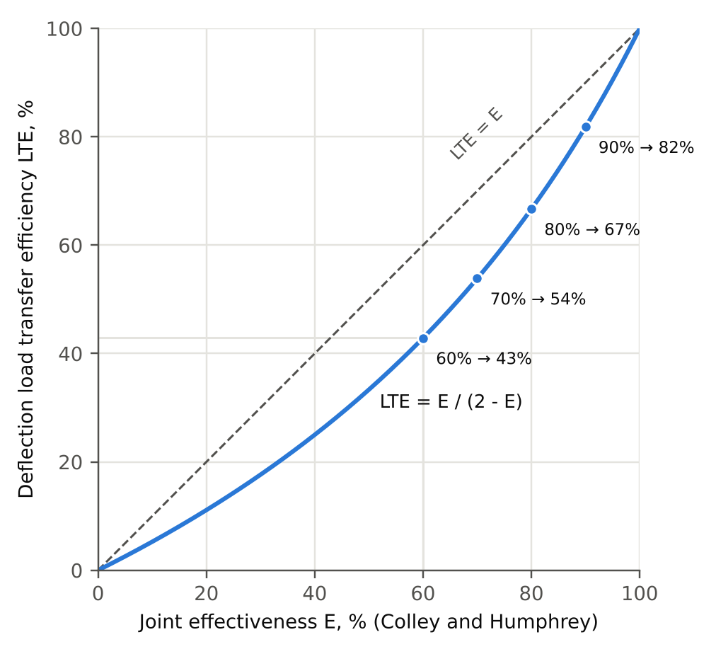
The case for enhanced aggregate interlock in ACI 360R-10 rests largely on PCA laboratory tests reported by Colley and Humphrey (9). The guide summarizes two results: joint effectiveness reduced to 60% at an opening of 0.025 in. (0.64 mm) for 7 in. (180 mm) slabs, and to 60% at 0.035 in. (0.89 mm) for 9 in. (230 mm) slabs. The same figures appear in PCA's 1983 Concrete Floors on Ground (18), which also described 50% joint effectiveness through one million load cycles, reached on sandy soils at about k = 200 pci (54 MPa/m), as "an acceptable percentage limit." Because 0.1% reinforcement is intended to hold joints near such widths, a value of 60% is easily read as acceptable performance.
Joint effectiveness, however, is not the deflection load transfer efficiency (LTE) used in current practice (10). Joint effectiveness is twice the unloaded-side deflection divided by the sum of the loaded- and unloaded-side deflections; LTE is the unloaded-side deflection divided by the loaded-side deflection. From those definitions, LTE = E / (2 - E), so 60% joint effectiveness corresponds to an LTE of about 43%, and PCA's 50% limit to about 33% (Figure 2). Read in the terms the industry now uses, the most favorable data the guide cites indicate that a joint at those widths transfers less than half of the deflection, not 60%. The derivation and further questions about the technical basis given for 0.1% reinforcement in ACI 360R-10 are addressed in a companion paper (11).
Design Comparison
Facility and Design Inputs
A single warehouse was designed with three joint details using SLABS (12), following the scenario used in an earlier comparison of seven slab types (13, 14). The facility is 172,800 sq ft (16,050 m²) with 60 by 60 ft (18 by 18 m) column bays and a 3:1 width-to-length ratio. Racks are six high with 2,000 lb (8.9 kN) pallets on 6 in. (150 mm) square base plates and 80% shelf utilization, giving 9,600 lb (43 kN) post loads, designed with an allowable stress ratio of 0.8 and a static modulus of subgrade reaction. The lift truck is a three-wheel reach truck with small, hard wheels carrying 3,000 lb (13 kN), designed with an allowable stress ratio of 0.45 for unlimited repetitions and a dynamic modulus of subgrade reaction. Subgrade resilient modulus is 5,800 psi (40 MPa), corresponding to dynamic and static k-values of 150 and 75 psi/in. (41 and 20 MPa/m). The slab is placed on a 15-mil vapor barrier with a friction coefficient of 0.50. The concrete has a 90-day to 28-day strength ratio of 1.1 and a coefficient of thermal expansion of 4.5 × 10⁻⁶/°F, with a setting temperature of 100°F (38°C) and a mean annual facility temperature of 70°F (21°C). A typical concrete mixture with relatively high shrinkage and curl is assumed for all three types.
Joint Details
All three designs use 15 ft (4.6 m) joint spacing and therefore the same joint layout. Type 1 (unreinforced) has dowels at construction joints only; its sawcut joints are expected to open about 0.13 in. (3.3 mm), giving an LTE below 4%. Type 2 (enhanced aggregate interlock) has dowels at construction joints and 0.1% deformed reinforcement through the sawcut joints, for which the model gives an LTE of 36.9%. Type 3 (strategically reinforced) has plate dowels at all joints, designed for 90% LTE (15).
Results
Table 1. Minimum Thickness for Three Joint Details in the Same Facility
| Type | Slab type | Sawcut joint detail | Sawcut joint LTE, % | Minimum thickness, in. |
|---|---|---|---|---|
| 1 | Unreinforced | Undoweled | < 4 | 10 |
| 2 | Enhanced aggregate interlock | 0.1% steel through joint | 37 | 9.5 |
| 3 | Strategically reinforced | Plate dowels | 90 | 7 |
The undoweled slab requires 10 in. (250 mm). Adding dowels to every joint, with no change in joint spacing, concrete, or curl, reduces the requirement to 7 in. (180 mm), a 30% reduction. The 0.1% reinforcement reduces it by only 0.5 in. (13 mm), to 9.5 in. (Table 1, Figure 3).
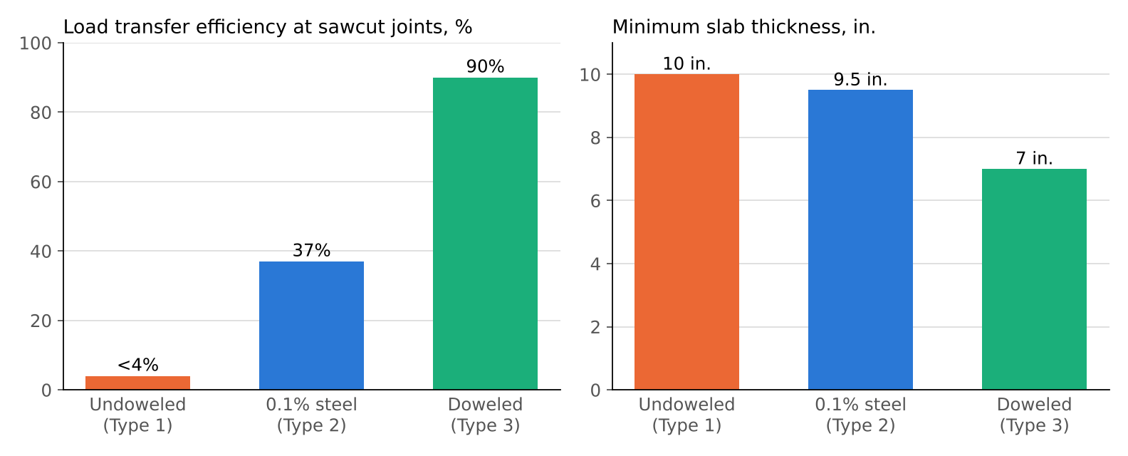
The reason is the stress at loaded joints. With LTE below 4%, a post or wheel at a sawcut joint is carried essentially as a free-edge load, and the edge stress governs thickness. With 90% LTE, the adjacent panel shares the load and the joint behaves much like the interior, so the governing stress falls and a thinner slab suffices. At 37% LTE, most of the load at the joint is still carried by the loaded panel alone, and the required thickness remains close to that of the undoweled slab. Mechanically, the 0.1% reinforcement detail performs closer to the undoweled slab than to the doweled slab.
Comparison With PCA Guidance
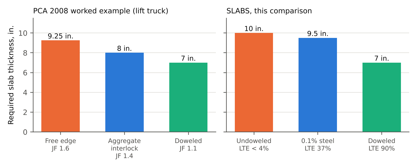
The 2008 PCA edition (4) includes a worked example for a single-wheel lift truck in which the loads, concrete, and subgrade are held constant and only the joint condition changes (Table 3). The doweled design, with a joint factor of 1.1 to allow for imperfect consolidation and random cracking, requires 7 in. (180 mm). The aggregate interlock design, with a joint factor of 1.4 selected for low-shrinkage concrete (600 microstrain) and short joint spacing, requires 8 in. (200 mm). The free-edge case, with a joint factor of 1.6 or the zero-load-transfer nomograph, requires 9.25 in. (230 mm).
Table 3. Required Thickness in the PCA (2008) Inch-Pound Single-Wheel Vehicle Example
| Joint condition | Joint factor | Thickness, in. | Relative to free edge |
|---|---|---|---|
| Free edge (zero load transfer) | 1.6 | 9.25 | 100% |
| Aggregate interlock | 1.4 | 8 | 86% |
| Doweled | 1.1 | 7 | 76% |
The doweled design is about 24% thinner than the free-edge design in the PCA example, compared with 30% in the SLABS comparison (Figure 4). The facilities and loads differ, but the pattern is the same, as expected for methods that rest on the same analysis lineage. The differences between the two also come from inputs and framework. PCA's 2008 joint factors rest on edge-stress calculations with the ILLI-SLAB finite element program, the predecessor of ISLAB2000 (4), but the PCA procedure remains an interior-load chart adjusted by a factor: it includes no curl, no loss of support, no conversion of beam strength to slab capacity, and none of the other enhancements in SLABS. PCA also applies a joint factor of 1.1, not 1.0, to its doweled case, to allow for imperfect consolidation beneath the dowels and for random cracking. A joint factor of 1.0, the idealized value PCA itself gives for full load transfer, would move the PCA result closer to the 30% reduction found here. Either way, the result depends on the inputs assumed and the framework used to evaluate them. The PCA aggregate interlock case also illustrates the sensitivity to shrinkage: its joint factor of 1.4 reflects a low-shrinkage mixture, and the guide's shrinkage-based table raises the factor toward 1.6 for the higher-shrinkage mixtures typical of first-cost spec construction and assumed for Type 1 here. A 3 in. (75 mm) difference between undoweled and doweled designs is therefore not an aggressive result, but one the standard method has indicated since the joint factor was introduced.
Relative Cost
Survey Method
Concrete flooring contractors priced the three designs using the approach the American Concrete Pavement Association has used in its contractor cost surveys since 1995. No dollar figures were collected. Each contractor estimated the in-place cost of the Type 1 slab for a project within 50 miles of its office and assigned it 100%, then estimated Types 2 and 3 as percentages of that baseline, holding all other features of the project constant. Responses were confidential, and only averaged results are reported. Joint filling and armoring were excluded, since the joint layout is the same for all three types.
Results
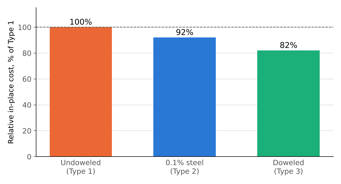
Table 2. Average Relative In-Place Cost Reported by Contractors
| Type | Slab type | Thickness, in. | Relative cost, % of Type 1 |
|---|---|---|---|
| 1 | Unreinforced (baseline) | 10 | 100 |
| 2 | Enhanced aggregate interlock | 9.5 | 92 |
| 3 | Strategically reinforced | 7 | 82 |
The doweled slab was the least expensive of the three at 82% of the undoweled cost, and the 0.1% reinforcement slab was intermediate at 92% (Figure 5). The dominant driver is concrete volume. The 3 in. (75 mm) reduction for Type 3 removes about 1,600 cu yd (1,220 m³) of concrete from the 172,800 sq ft (16,050 m²) floor, along with associated placing and finishing effort, which more than offsets the cost of dowels at the sawcut joints. The 0.5 in. (13 mm) reduction for Type 2 removes about 270 cu yd (206 m³), most of which is offset by the cost of supplying, supporting, and placing the reinforcement.
Ownership Cost and Joint Performance
The three designs have identical joint layouts, about 22,000 linear feet of interior joints in this facility, so joint count does not distinguish them at construction. It does distinguish them in service. Joints that rely on aggregate interlock, with or without light reinforcement, are prone to relative movement of the joint edges under traffic, failure of joint filler, and edge spalling, and the resulting repairs recur over the life of the floor (16). ACI 360R-10 gives joint stability limits on differential deflection under traffic of 0.010 in. (0.25 mm) for small hard wheels and 0.020 in. (0.51 mm) for large cushioned wheels (1, 17). Joints with engineered load transfer are the most reliable way to stay within them. ACI 360R-10 also raises the risk of dominant joints directly in its own guidance. Section 6.2 notes that vapor retarders, which reduce base friction, make dominant joints "more noticeable and problematic," and the 0.1% steel detail relies on a doweled joint at a maximum of 125 ft (38 m) to force activation where the reinforced sawcut joints do not activate. A dominant joint concentrates the movement of several panels at one location, so the joints most likely to need repair are the ones the guide's own details create. In the authors' experience, and in the experience of owners and operators who maintain floors of each type, long-term joint maintenance spending is much lower where joints have engineered load transfer. On that basis, the undoweled slab is not only the most expensive of the three to build in this comparison but also likely the most expensive to own.
Discussion
The results do not support assigning the same thickness to doweled, undoweled, and lightly reinforced slabs. For the facility considered, holding thickness constant would either waste about 3 in. (75 mm) of concrete in the doweled slab or, if a doweled thickness were adopted for the other two, leave them underdesigned for loads at joints. The second error is the more serious, and it is the one encouraged when joint details are treated as alternates on a fixed slab.
The results also do not support treating 0.1% reinforcement as equivalent to dowels in thickness design. Both the model result of 37% LTE and the 43% LTE implied by the PCA data cited in ACI 360R-10 place the detail much closer to an undoweled joint than to a doweled joint. Designing it with interior-load assumptions, or with the thickness of a doweled slab, overstates its capacity for loads at joints.
Finally, the method most often used for spec buildings already accounts for this. PCA introduced joint factors for vehicle and post loads in 2001 to begin closing the gap left by interior-load design, and in 2008 added free-edge charts for vehicles and tied the joint factor to shrinkage. ACI 360R-10 references the 2001 edition but does not draw attention to the distinction, and spec slabs are often designed as though it did not exist. Designers using ACI 360R-10 should apply the joint factor of the PCA edition they follow, or use a mechanistic method that models load transfer at each joint directly.
Limitations
The comparison represents one combination of loads, support, concrete, climate, and joint layout, and the differences between types will vary with these inputs. LTE values are model estimates for the stated conditions. The relative cost results are averages of contractor estimates rather than bid prices, exclude joint filling and armoring, and do not include maintenance costs, which are discussed qualitatively. A survey of long-term joint maintenance costs by joint type would strengthen the ownership cost comparison.
Conclusions
Spec building floors designed by reference to ACI 360R-10 are, for thickness, designed to the 2001 PCA method, which includes joint factors for vehicle and post loads near joints; the 2008 edition adds free-edge charts for vehicles. For a 172,800 sq ft (16,050 m²) warehouse with identical joint layouts, a mechanistic-empirical design gave minimum thicknesses of 10 in. (250 mm) undoweled, 9.5 in. (240 mm) with 0.1% reinforcement, and 7 in. (180 mm) with dowels, corresponding to sawcut joint LTE values below 4%, 37%, and 90%. Contractor relative costs were 100%, 92%, and 82%. PCA's own 2008 worked example shows the same pattern, with a doweled slab about 24% thinner than a free-edge slab. The aggregate interlock data cited in ACI 360R-10 are joint effectiveness values whose 60% corresponds to about 43% LTE. Doweled and lightly reinforced slabs should not share a thickness; 0.1% reinforcement performs closer to an undoweled slab; and the doweled slab was both the least expensive to build and, with stable joints, the least expensive to own.
Acknowledgments
The authors thank the contractors who contributed cost data.
References
1.ACI Committee 360. Guide to Design of Slabs-on-Ground. ACI 360R-10. American Concrete Institute, Farmington Hills, Mich., 2010.
2.Farny, J. A. Concrete Floors on Ground, 3rd ed. EB075. Portland Cement Association, Skokie, Ill., 2001.
3.Packard, R. G. Slab Thickness Design for Industrial Concrete Floors on Grade. IS195.01D. Portland Cement Association, Skokie, Ill., 1976.
4.Farny, J. A., and S. M. Tarr. Concrete Floors on Ground, 4th ed. EB075. Portland Cement Association, Skokie, Ill., 2008.
5.Tabatabaie, A. M., and E. J. Barenberg. Structural Analysis of Concrete Pavement Systems. Transportation Engineering Journal, Vol. 106, No. 5, 1980, pp. 493-506.
6.Khazanovich, L., H. T. Yu, S. Rao, K. Galasova, E. Shats, and R. Jones. ISLAB2000: Finite Element Analysis Program for Rigid and Composite Pavements, User's Guide. ERES Consultants, Champaign, Ill., 2000.
7.ARA, Inc. Guide for Mechanistic-Empirical Design of New and Rehabilitated Pavement Structures. NCHRP Project 1-37A Final Report. Transportation Research Board, Washington, D.C., 2004.
8.Covarrubias, J. P., R. Rodden, L. Khazanovich, J. Roesler, and N. Parkes. Mechanistic-Empirical Design of Concrete Slabs-on-Ground. Concrete International, July 2026.
9.Colley, B. E., and H. A. Humphrey. Aggregate Interlock at Joints in Concrete Pavements. Highway Research Record 189, Highway Research Board, Washington, D.C., 1967. http://onlinepubs.trb.org/Onlinepubs/hrr/1967/189/189-001.pdf.
10.Snyder, M. B. Guide to Dowel Load Transfer Systems for Jointed Concrete Roadway Pavements. National Concrete Pavement Technology Center, Iowa State University, Ames, 2011. https://intrans.iastate.edu/app/uploads/2018/08/Dowel-load-guide.pdf.
11.Rodden, R. Reinforcement Continued Through Sawcut Contraction Joints in Slabs-on-Ground: Limits of a Section-Level Shrinkage Solution. Manuscript in preparation, 2026.
12.The Slab Designer, LLC. SLABS. https://slabs.design. Accessed October 2026.
13.Covarrubias, J. P., N. Parkes, and B. Birdwell. Concrete Slab Design Options & Analysis. ForConstructionPros, January 2026.
14.Covarrubias, J. P., N. Parkes, and R. Rodden. Concrete Slab-on-Ground Thickness Requirements from Modern Design. ForConstructionPros, July 2026.
15.Parkes, N., J. Olavarría Bastidas, and R. Rodden. Optimize Concrete Slab Dowel Design. ForConstructionPros, October 2025.
16.Walker, W. W., and J. A. Holland. The Hidden Cost of Aggregate Interlock. Concrete Construction, Vol. 52, No. 2, 2007, pp. 36-41.
17.Walker, W. W., and J. A. Holland. Performance-Based Dowel Design. Concrete Construction, Vol. 52, No. 1, 2007, pp. 72-84.
18.Spears, R. E., and W. C. Panarese. Concrete Floors on Ground. EB075.02D, 2nd ed. Portland Cement Association, Skokie, Ill., 1983.
Related in This Series
- Article on this topic: Spec Building Floors: Why Undoweled, Doweled, and 0.1% Steel Slabs Should Not Share One Thickness
The joint detail changes how thick a spec building slab needs to be, and the cost numbers say doweling pays.
- Joint Spacing, Curling, and the Factor of Safety in ACI 360R-10
Checks the Fig. 6.6 joint spacing and the Table 5.2 factor of safety against the guide's own curling and fatigue data.
- Reinforcement Continued Through Sawcut Contraction Joints
Shows the section-level solution behind the 0.1% limit does not address force transfer across a joint or redistribution of opening.
- The Modulus of Subgrade Reaction for Slabs-on-Ground
Compares CBR-to-k correlations with a calibrated elastic layered method and evaluates the SSI long-term k-value approach.
- Light Reinforcement Through Sawcut Joints: Tolerances and the JRCP Record
Thickness tolerances push as-built steel ratios past 0.1%, and the highway record of JRCP shows where that detail leads.
Revision history
- November 8, 2026: Noted the OptiPave to OptiSlab lineage of the SLABS surrogate model.
- November 4, 2026: Added metric units to k-values.
- November 3, 2026: Renumbered slab types (enhanced aggregate interlock is now Type 2); added PCA framework and joint factor discussion and the dominant joint risk raised in ACI 360R-10; added metric units.
- October 30, 2026: Added links to later pieces in the series.
- October 29, 2026: First published on slabs.design/knowledge.
To cite this paper, use the citation printed in the PDF. It includes the revision date, so readers can match your citation to the text you read.