Article|TSD-01A
Corduroy Roads to Pavement ME: What a Century of Concrete Roads Can Teach Floors
Every detail in a concrete pavement is the answer to a problem somebody had. Floors borrowed most of those answers, and skipped one important lesson.
Robert Rodden (The Slab Designer, LLC); Juan Pablo Covarrubias (TCPavements-FORTA)
The Slab Designer, LLC | Published October 20, 2026 | Revised November 8, 2026
About a dozen years ago, when one of us (Robert) was at the American Concrete Pavement Association, ACPA's resident history buff, Larry Scofield, talked him into a project: document the "why" and the "how" of concrete pavement design. Why are joints spaced the way they are? Why are dowels smooth? Why do highway pavements have either no steel or a lot of it, and almost never a little?
Robert has given some version of that presentation more than a dozen times since. The short answer is always the same: trial and error, and a lot of it. Keep your eyes peeled for the corduroy road.
It started with ruts, not structure
Before concrete, a "good" road might be a corduroy road: logs laid side by side across the path so wagons wouldn't sink in the mud. The first concrete pavement in the U.S., around the courthouse square in Bellefontaine, Ohio, in 1891, wasn't designed for loads at all. It was built because horseshoes and steel wagon wheels rutted everything else. Thickness was judgment. Joints were wherever one batch ended and the next began, usually 6 to 8 feet (1.8 to 2.4 m) apart because that's what the mixer could make.
Those short slabs were never designed to control cracking, but they did. That's worth remembering, because the next 50 years were mostly about relearning it.
Longer slabs, then cracks, then steel
As speeds went up, drivers complained about all the rough hand-formed joints, and contractors wanted fewer of them anyway. Slabs got longer and wider. And concrete did what concrete does: it shrank, the ground restrained it, and it cracked.
Engineers tried a little of everything. Thickened centers to fight longitudinal cracks. Tooled joints. Thickened edges once the Bates test road in Illinois showed that edge stresses governed. Expansion joints, which turned out to close up over the years and push extra movement into the contraction joints next to them. That last one is the first clear lesson in the record, and it keeps coming back: restrain or free one joint, and you change what happens at its neighbors.
To hold the cracks in long panels together, designers added a little steel. That became jointed reinforced concrete pavement, or JRCP: joints 40 to 100 feet (12 to 30 m) apart, about 0.1% to 0.25% steel, and cracks every 15 to 20 feet (4.6 to 6.1 m) in between. By the 1930s, most concrete highway pavement in the U.S. was built that way.
Westergaard and the k-value
In 1926, H. M. Westergaard at the University of Illinois gave engineers the first rational way to design thickness. He modeled the slab as a plate on a bed of springs, described by a single number, the modulus of subgrade reaction, or k-value, and showed that loads at edges and corners produce much higher stress than loads in the middle. PCA built its pavement design on his work in the 1930s, and later its floor design.
Westergaard's spring model is still the foundation of every thickness method in ACI 360R-10. That's both a credit to him and a problem for us, because he assumed the slab is always in full contact with the ground. But as Walker and Holland reminded the industry back in 1999, all slabs curl. And a curled slab isn't in full contact.
What the roads decided
After World War II, practice split. Some agencies built short-jointed plain pavement. Others kept building long-jointed JRCP. Sawing joints in hardened concrete (1940s) and slipform paving (1949) made short-jointed plain pavement the cheapest to build. Then the AASHO Road Test (1958 to 1960) and decades of national performance studies told the agencies which pavements actually held up.
JRCP didn't fare well. The light steel just wasn't enough to keep the intermediate cracks tight, all things considered. The cracks opened far enough that aggregate interlock was lost, and there wasn't enough steel to carry the load across on its own, so the cracks faulted and spalled. The FHWA performance study that came out of that era recommended at least 0.1% steel for JRCP. A minimum, not a ceiling.
That's also why a strategically reinforced floor (dowels at every joint and nothing else) puts its steel where it does. Steel does nothing until the concrete cracks, so it only earns its keep where there's a crack through it. In a 15-foot (4.6 m) panel sized for curl and load to stay uncracked, the 0.1% steel running through the middle of the panel adds cost and no value; only the bars crossing the joints do any work. Dowels take the other approach: size the panel right, and put the steel only at the joints, the weak point, where it pays back. At the joint itself, dowels typically put roughly ten times as much steel across the crack as a 0.1% layer does. The Slab Designer's JOINTS tool runs that comparison for a given layout.
The agencies kept the two ends and dropped the middle:
- Jointed plain pavement, with short joint spacing and dowels where traffic is heavy. Minimize restraint and let every joint open a little.
- Continuously reinforced pavement, with about 0.6% steel and no transverse joints. Maximize restraint and force lots of fine, tight cracks.
Here's our favorite insight from that history. The very existence of continuously reinforced pavement is evidence that a little steel didn't solve the problem. When light steel in long panels didn't work, engineers did what was trendy with concrete. They added more steel.
Today, the national mechanistic-empirical design method, AASHTOWare Pavement ME, covers jointed plain and continuously reinforced pavement only. Its manual of practice says JRCP "cannot be designed using this procedure." Texas, one of the last holdouts, says JRCP "is no longer endorsed by the department."
The short-jointed end of that convergence has since been pushed about as far as it can go. In 2005, one of us (Juan Pablo) introduced a concept in Chile that sizes the panels to the truck instead of to a rule of thumb: make each panel small enough that only one wheel, or one set of wheels, loads it at a time. Smaller panels curl less and share less load. According to its developers, that lets the slab be thinner for the same life, and the joints open so little that the sawed joints don't need dowels. It's the same lesson the roads learned the hard way, minimize restraint, taken to its logical end with geometry instead of steel. It also wasn't a guess. The method was built on finite element analysis, calibrated with accelerated load testing at the University of Illinois, released as the OptiPave software in 2010, and recognized in ACI 330.2R-17. Chile's Ministry of Public Works has more than a decade of performance data on the projects it built.
Meanwhile, on the floor
Floors borrowed almost all of their design theory from roads, and they say so. PCA's floor manual leans on pavement research throughout, justifying the k-value because "substantial pavement research has shown" it predicts slab deflections and stresses reasonably well. The k-value, the Westergaard solutions, the thickness charts, and the aggregate interlock data in ACI 360R-10 all came from pavement research.
Where floors pulled ahead was construction. Laser screeds, F-numbers for flatness, early-entry saws, plate dowels, fibers, shrinkage-compensating concrete, post-tensioning. The floor industry innovated faster than the road industry in a lot of ways.
Design is another story. ACI 360R-92 was 57 pages from a committee of 11. The 2006 edition was introduced in a structural magazine as bringing slab design "into the 21st Century." It added a great deal, but its thickness methods were still the Westergaard-based procedures from the 1920s through the 1970s. Meanwhile, pavement design moved to mechanistic-empirical methods that include curling, loss of support, and load transfer that depends on how wide a joint opens.
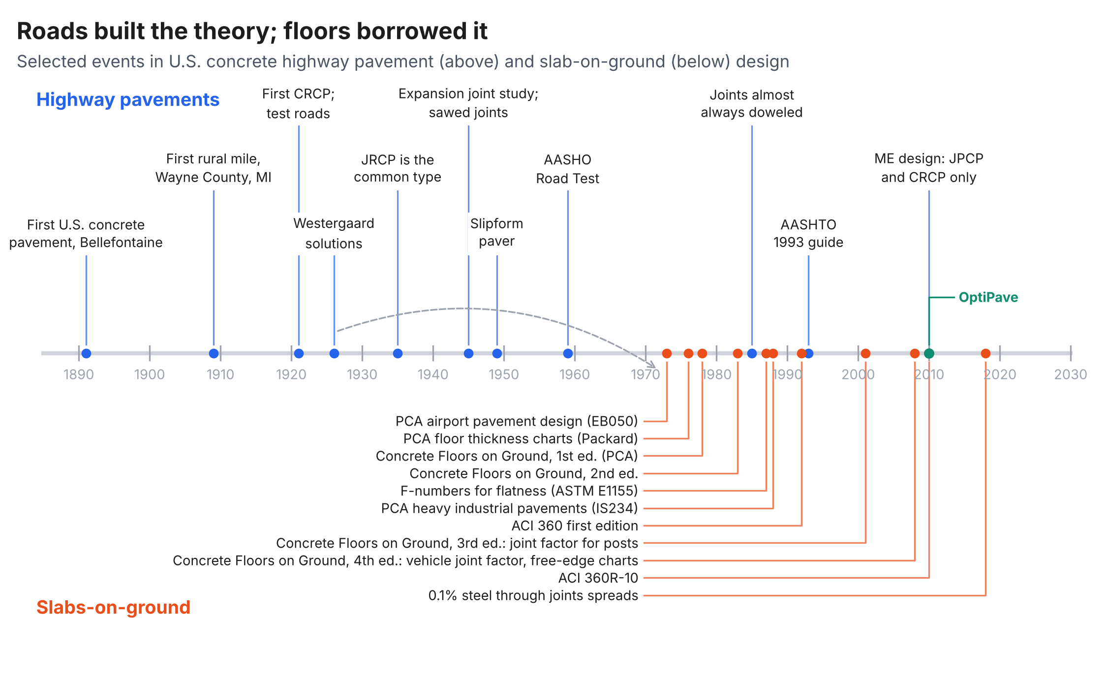
That route has started to reach floors, and it came from the road side, not from the PCA charts. Juan Pablo took the approach behind OptiPave, finite element runs used to train neural networks, and applied it to industrial floors in stages: rack loads first, then forklifts, point loads, and distributed loads. By 2021 it was a single floor design tool, OptiSlab, that computes top-down and bottom-up stresses, includes curl, accounts for panel size, and uses an allowable stress that reflects the difference between a slab and a lab beam. By Juan Pablo's records, it's been used on more than 600 projects in seven countries. Full disclosure: Juan Pablo developed OptiPave and OptiSlab, and that work is now being carried into SLABS, our own platform, so neither of us is a neutral observer. But the point stands on its own. Mechanistic-empirical floor design isn't a someday idea. It's being done.
And then there's the one borrowing that runs backward in time. Over the last couple of decades, floors have increasingly used 0.1% steel continued through sawcut joints, with doweled joints every 125 feet (38 m) or so. ACI 360R-10 calls it "enhanced aggregate interlock." Look at the layout and the steel. It's JRCP with the cracks sawed in a straight line. Even the number matches. FHWA recommended 0.1% as a minimum for JRCP, the least steel that might keep the cracks tight, with more for harsher conditions. ACI 360R-10 gets to 0.1% another way, with a structural calculation showing the steel restrains under 3% of the shrinkage. Walker and Holland's "Courthouse Zone" then makes exactly 0.1% through the joints the one acceptable amount short of continuous reinforcement, and anything between 0.1% and 0.5% the zone to avoid. That zone is essentially the JRCP steel range, and its name fits the JRCP record. On the roads, the answer to that record was to leave the range: no distributed steel, or a lot of it. On floors, the answer has been to sit right at its bottom edge. Floors picked up the one highway type the highway agencies decided not to keep.
Six lessons from the roads
- Restraint drives jointed slab behavior. Tie some joints and free others, and the movement goes somewhere. Figure out where before the racks go in.
- The ends work; the middle is fragile. Short-jointed plain slabs and fully continuous slabs both have long records. The in-between type depends on every bar and every joint working exactly as intended for decades.
- Load transfer is structural. Faulting is what drove the roads to dowels. A floor designed for loads in the middle of a panel is quietly assuming its joints work perfectly.
- Fix support at the source. The roads solved pumping with subbases, drainage, and stabilization, not with steel in the slab. Steel holds cracks together after they form. It doesn't stop them from forming.
- Design follows data. Pavement methods got better as national performance data piled up. Floors would benefit from the same thing: joint openings, curl, and cracking, measured and tied back to the design details.
- Mechanistic-empirical design is available. Highways have used it for more than a decade, and the path from pavement software to floor software has already been walked. There's no technical reason floors can't use it.
The roads paid for these lessons with a century of trial and error and decades of federally funded performance studies. Floors don't have to pay for them again. We just have to read the record.
Sources
AASHTO, Mechanistic-Empirical Pavement Design Guide: A Manual of Practice, American Association of State Highway and Transportation Officials, 2008.
ACI Committee 330, ACI 330.2R-17, Guide for the Design and Construction of Concrete Site Paving for Industrial and Trucking Facilities, American Concrete Institute, 2017.
ACI Committee 360, ACI 360R-10, Guide to Design of Slabs-on-Ground, American Concrete Institute, 2010.
Covarrubias, J. P., "History of OptiSlab: From Research Idea to Production-Ready Engineering Software," presentation, LTPisos, March 2026.
Covarrubias, J. P., Del Rio, P., and Fernández, M., "Performance of Concrete Pavements with Optimized Geometry Panels Tendered by the Ministry of Public Works in Chile," 13th International Conference on Concrete Pavements, Minneapolis, 2024.
Farny, J. A., and Tarr, S. M., Concrete Floors on Ground, EB075, 4th ed., Portland Cement Association, 2008.
Portland Cement Association, Concrete Floors on Ground, EB075, 3rd ed., Portland Cement Association, 2001.
McKinney, A. W., "ACI 360R-06 Brings Slabs on Ground Design into the 21st Century," STRUCTURE Magazine, January 2007.
Smith, K. D., et al., Performance of Jointed Concrete Pavements, FHWA-RD-89-138, Federal Highway Administration, 1990.
Texas Department of Transportation, Pavement Manual, Section 4.7, Jointed Reinforced Concrete Pavement.
Walker, W. W., and Holland, J. A., "Stay out of the Courthouse Zone," Engineering Bulletin, Structural Services, Inc., 2016.
Walker, W. W., and Holland, J. A., "The First Commandment for Floor Slabs: Thou Shalt Not Curl Nor Crack... (Hopefully)," Concrete International, Vol. 21, No. 1, January 1999.
Westergaard, H. M., "Stresses in Concrete Pavements Computed by Theoretical Analysis," Public Roads, Vol. 7, No. 2, 1926.
Related in This Series
- Technical paper on this topic: The Evolution of Concrete Pavement Design and Its Lessons for Slabs-on-Ground
A century of pavement design organized around the problems that drove it, set alongside the development of slabs-on-ground.
- When Concrete Has No Competition
Industrial floors innovated without an industry program behind them. The guidance hasn't kept up.
- Thickness Ain't Nothin' but a Number
Why the thickest slab is often the least engineered one, and what the roads learned when they measured it.
- The Design Guide a New Engineer Can't Design From
A new engineer follows ACI 360R-10 step by step and finds the places it raises an issue and stops.
- The Floor Design Guide That Calls Its Own Results Erroneous
What owners should know about the trap built into the industry's main slab design guide.
Revision history
- November 8, 2026: Added optimized-geometry slabs, OptiPave, and the path to floor design through OptiSlab; updated Figure 1.
- November 4, 2026: Revised the 0.1% and Courthouse Zone discussion; added the timeline figure; replaced the dowel steel comparison with why steel belongs at the joints.
- October 27, 2026: Revised the JRCP crack performance discussion; added FHWA's 0.1% minimum versus the Courthouse Zone; added metric units.
- October 20, 2026: First published on slabs.design/knowledge.
To cite this article, use the citation printed in the PDF. It includes the revision date, so readers can match your citation to the text you read.