Technical Paper|TSD-04TP
Raised but Not Resolved: An Audit of Design Completeness in ACI 360R-10
The Slab Designer, LLC | Published October 23, 2026 | Revised November 4, 2026
Abstract
A design guide is complete for a given decision when it states the issue, gives the designer a way to quantify it, and shows that quantification in a worked example; it is honest when, lacking a method, it says so and points elsewhere. This paper audits ACI 360R-10, Guide to Design of Slabs-on-Ground, against that standard by reading it the way an engineer one or two years out of school would when handed a speculative warehouse floor: a reach truck on small, hard wheels, back-to-back pallet racks, and a choice between undoweled sawcut joints, doweled joints, and 0.1% steel through the sawcuts. Following the guide in order, the designer can produce a thickness from an interior-load chart, but cannot carry out a series of instructions the guide itself gives: consider loads near joints, design for curl, evaluate joint opening, choose a k-value suited to each load, and set a factor of safety from the listed considerations. The audit records 25 findings, each tied to section numbers in the published guide, in six groups: the thickness methods, joints and load transfer, subgrade support, loads and factors of safety, distributed loads, and editorial errors that send a reader to the wrong place. Several are internal conflicts. The methods are called generally accepted, erroneous, and reasonable in three chapters. Four statements give the joint spacing chart four different purposes. Four sections give three bases for the factor of safety, and the guide's own PCA examples, at factors of safety of 1.7 and 1.4, correspond to about 40,800 and 1,450 allowable repetitions in its Table 5.3, while it states floors are often designed for unlimited repetitions. The 60% joint effectiveness the guide cites corresponds to about 43% load transfer efficiency, and the same opening is called both 60% effective and ineffective. The fiber-reinforced appendix assumes 20% load transfer at a sawcut joint and no curling stress at the edge, while the COE method assumes a 0.75 transfer coefficient at every joint and Chapter 14 places the worst curling effect at the edges. The paper proposes a completeness criterion for future editions and lists the specific additions that would close each gap.
Keywords: ACI 360R-10, design guidance, slab-on-ground, factor of safety, curling, joints, dowels, k-value, design procedure
Introduction
Guidance for practitioners has to be written for engineers with different backgrounds, for owners and contractors who read it differently, and for situations its authors cannot fully anticipate. The author spent nearly a decade writing such guidance at the American Concrete Pavement Association and is aware how easy it is to fall short. The test the author's colleagues tried to apply there was simple: if a document raises an issue, it should carry it through, either with a method, numbers, and an example, or with a plain statement that the method does not cover it and a pointer to one that does.
A goal repeatedly voiced within the slab-on-ground community is that ACI 360 should be clear and direct enough that an engineer new to the field can use it to design a slab. This paper takes that goal as its criterion and applies it to the published 2010 edition (1). It does not address any revision in progress. Section, table, figure, and appendix numbers refer to ACI 360R-10 as published.
Method
The audit assumes a realistic first assignment: a speculative distribution warehouse with a reach truck on small, hard polyurethane wheels, back-to-back pallet racks, and three joint options under consideration (undoweled sawcut joints with dowels at construction joints only, doweled joints throughout, and 0.1% deformed steel continued through the sawcuts). The designer is careful, follows the guide in order, and assumes that what it says is complete and current.
At each step the question is the same: can the designer do what the guide says, with what the guide provides, and get a defensible answer? Where the answer is no, the finding records what the guide says, why it stops the designer, what newer or more complete guidance exists, and a suggested fix. Where the guide's own inputs allow a quantitative check, the check is performed with closed-form methods or tables the guide itself contains. Issues with 0.1% steel through sawcut joints are covered in detail in companion papers (2, 3) and are summarized here briefly.
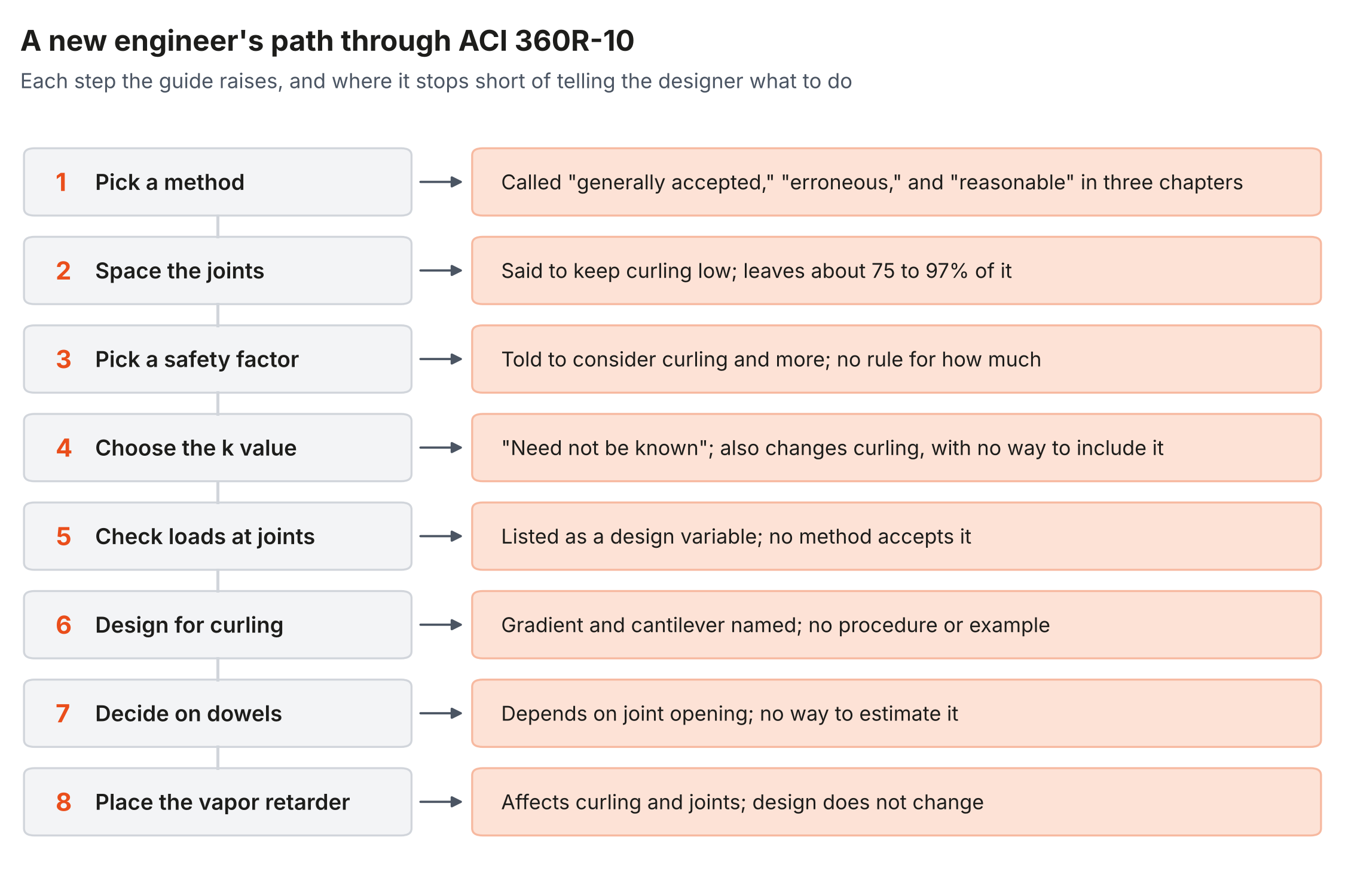
Walking Through a Design
- Pick a method. Chapter 7 offers the PCA, WRI, and COE methods as "generally accepted." The designer picks PCA because it is the most widely used and the only one with post-load charts. Section 14.13 later says all three "give erroneous results" where the slab has lost contact with the subgrade, but Chapter 7, where the method is chosen, does not say what to do about it (Findings 1, 5).
- Get the edition. Appendix 1 says its charts are from PCA's 2001 edition. The designer does not learn that PCA's 2008 edition added free-edge charts and a joint factor of up to 1.6, and the guide's examples use interior charts only (Finding 2).
- Pick k. Section 4.4.9 says a higher k can be used for rolling loads, so the reach truck and the racks should not share a k-value, but Chapter 4 gives no way to obtain either value, and Section 4.5.2 says the exact value need not be known (Findings 14, 15).
- Size the truck wheels. The guide notes that polyurethane tire pressures exceeding 1000 psi (6.9 MPa) have been measured but gives no direction on using the charts for such wheels. Its worked example assumes a 25 sq in. contact area (Finding 17).
- Pick a factor of safety. Four sections give three different bases for it. The worked lift truck example uses 1.7, which the guide's own Table 5.3 limits to about 40,800 repetitions; the rack example uses 1.4 (Finding 16).
- Check the racks. The back-to-back posts are much closer across the flue than the example spacing, and there is no way to account for posts near joints, even though Chapter 5 lists joint location and shear transfer as design variables (Findings 3, 18).
- Decide on dowels. The guide says to dowel where joints open more than 0.025 to 0.035 in. (0.64 to 0.89 mm) but never shows how to estimate joint opening (Finding 9). For the 0.1% steel option, it gives no load transfer value to design with (Finding 12).
- Check edges and curl. The guide says enclosed slabs should be designed for a 3°F to 6°F per inch (1.7 to 3.3°C per 25 mm) upward-curling gradient and that the outer 3 to 5 ft (0.91 to 1.5 m) might be designed as a cantilever, with no procedure. Finite element analysis is endorsed in principle, with no modeling guidance (Findings 5, 8).
At the end, the designer has a thickness from an interior chart and a list of instructions that could not be followed. That thickness is the same whether the joints are doweled or not, which is the outcome PCA changed its method in 2001 and 2008 to prevent (4).
Table 1. Summary of Findings
| No. | Issue | Where in ACI 360R-10 | Type |
|---|---|---|---|
| 1 | The methods are called generally accepted, erroneous, and reasonable | 7.2; 14.13; 4.4.7; 5.8 | Conflict |
| 2 | The method cites PCA 2001; the joint factor and free-edge charts are missing | 7.2.1; 7.3; 5.9; 8.3; App. 1 | Outdated |
| 3 | Chapter 5 lists design variables that no method accepts | 5.3; 5.4; 5.5; 7.2.1.2 | Gap |
| 4 | Edge and corner equations are given with no way to use them | 7.2, Cases 1 to 3 | Gap |
| 5 | Designers are told to design for curl, but no method accepts it | 7.2; 14.13; 1.6 | Gap |
| 6 | The COE method is described three ways and credits every joint equally | 7.2; 7.2.3; App. 3 | Conflict / outdated |
| 7 | The WRI method has no source and incomplete inputs | 7.2.2; App. 2; Ch. 15 | Outdated |
| 8 | Finite element analysis is endorsed but not explained | 1.4.3; 11.3.3.4 | Gap |
| 9 | The dowel trigger depends on a joint opening the guide never estimates | 7.3; 14.12; 6.2; 9.1.1; Table 6.1 | Gap / conflict |
| 10 | Joint effectiveness is reported, but designers think in LTE | 6.2 | Gap |
| 11 | The purpose of Fig. 6.6 is described four ways | Fig. 6.6; 6.2; 4.4.7; 5.8 | Conflict |
| 12 | The 0.1% steel slab type has no load transfer value | 6.2; Table 6.2; 8.2 | Gap / conflict |
| 13 | Vapor retarders help, hurt, and worsen joints, with no design consequence | 4.6.7; 14.1; 14.8; 14.15.1; 6.2 | Conflict |
| 14 | Which k to use for which load is never defined | 4.4.3; 4.4.8; 4.4.9 | Gap |
| 15 | Thickness is said to be insensitive to k, while k governs edges | 4.5.2; 4.4.8; 14.13 | Conflict |
| 16 | Three bases for the factor of safety; examples imply limited repetitions | 5.2; 5.9; 7.1; 11.3.2.5; App. 1 | Conflict |
| 17 | Lift truck data and contact areas do not fit today's trucks | 5.2; Table 5.1; 7.2.1.1; App. 1 | Outdated / gap |
| 18 | Rack layouts outside the example spacing are not addressed | 5.3; 7.2.1.2; App. 1 | Gap |
| 19 | The fiber-reinforced yield-line example mixes load transfer, curl, and safety bases | App. 6; 11.3.3.3 | Conflict |
| 20 | Table A1.2 is mislabeled | App. 1, Table A1.2 | Error |
| 21 | Cross-references point to the wrong chapters | 4.4.1; 5.8; 7.2 | Editorial |
| 22 | Constants differ by method without explanation | 7.2; 7.2.3; App. 2; App. 6; Table 6.2; 14.12 | Editorial / conflict |
| 23 | Dated theory and sources | 1.4.2; 14.13; Tables 5.1 and 6.1; Fig. 4.3 | Outdated |
| 24 | A typographical error reverses a design value | 13.3 | Editorial |
| 25 | Fig. 6.6 keeps a note for lines that were removed | Fig. 6.6, Note 2 | Editorial |
A. Choosing and Running a Thickness Method
1. The Methods Are Called Generally Accepted, Erroneous, and Reasonable
Section 7.2 lists the PCA, WRI, and COE methods as "generally accepted," notes that "all three methods assume that the slab remains in full contact with the ground at all locations," and states: "Curl-induced stresses are not considered." Section 14.13 states that, because the three methods assume full support, "they give erroneous results for slab thickness where the slab is not in contact with the subgrade." Section 4.4.7 states that "by following the joint recommendations in Fig. 6.6, the curling stresses will be sufficiently low that the PCA, WRI, and COE methods will provide reasonable solutions," and Section 5.8 says the same of restraint stresses.
The Section 14.13 statement is not new. The committee's first guide, ACI 360R-92, carried it in nearly the same words, with the same three methods and the same note that a higher subgrade modulus permits a thinner slab while lengthening the unsupported curled edge (12). The conflict has stood through three editions.
A new designer is told the methods are acceptable, that they are erroneous wherever the slab has curled, and that they are fine as long as Fig. 6.6 is followed. Section 14.1 reports that curling stresses "can easily range from 200 to 450 psi," comparable to the entire allowable stress in a typical design. Applying the Westergaard-Bradbury formula the guide cites, with its coefficient of thermal expansion and recommended gradients, panels at the Fig. 6.6 spacings develop 75% to 88% of the maximum curling coefficient on k = 100 psi/in. (27 MPa/m) and 90% to 97% on k = 200 psi/in. (5). Nothing in the guide supports the "sufficiently low" statement.
Suggested fix: state in Chapter 7, where the method is chosen, what each method does not cover and what the designer should do instead; delete the "sufficiently low" statements in Sections 4.4.7 and 5.8 or support them with numbers.
2. The Method Cites PCA 2001, and the Joint Factor Is Missing
Appendix 1 presents "design charts published by PCA in Concrete Floors on Ground (2001)," and Sections 5.9, 7.3, and 8.3 cite the same edition. Section 7.2.1 states that "the PCA method is for interior loadings only; that is, loadings are not adjacent to free edges." Both worked examples (A1.2, lift truck; A1.3, rack posts) select thickness from interior charts.
PCA's 2001 edition applies joint factors to loads at joints, and its 2008 edition (6) extends the treatment, with a joint factor of 1.0 to 1.6, free-edge charts for vehicles, and edge charts for posts. In PCA's own 2008 metric lift truck example, the same truck, concrete, and subgrade give 7.1 in. (180 mm) doweled, 8.1 in. (205 mm) with aggregate interlock, and 9.3 in. (235 mm) at a free edge (4). The guide's procedure and examples produce one thickness regardless of the joint detail.
Suggested fix: reference the 2008 edition (now published by the American Cement Association), and work the Appendix 1 examples with joint factors of 1.0, about 1.4, and 1.6, so the effect of the joint detail on thickness is visible.
3. Chapter 5 Lists Design Variables That No Method Accepts
Section 5.3 lists, among the concentrated load variables, the "location of the concentrated load relative to slab joint location and the amount of shear transfer across the slab joint." Section 5.4 lists the "presence of a joint located in and parallel to an aisle" for distributed loads, and Section 5.5 lists "the amount of shear transfer across the slab joint" for line loads crossing or next to joints. Section 7.2.1.2 says to "consider also the proximity of rack posts to joints."
None of the methods in Appendixes 1 to 3 has an input for joint location or load transfer, and the guide gives no procedure for considering them. A new designer cannot act on the instruction.
Suggested fix: for each listed variable, point to the step or chart where it enters the design; where none exists, say so and give the alternative (the PCA joint factor, or analysis with load transfer at joints).
4. Edge and Corner Equations Are Given With No Way to Use Them
Section 7.2 presents Westergaard's corner, interior, and edge cases (Eqs. 7-1, 7-4, and 7-5) "to illustrate the effect of load location, particularly at free corners or edges," and states: "Most of the generally used structural design methods discussed do not provide for loading at free edges and corners. The designer should carefully consider such loading."
The equations assume a free edge with no load transfer and full support. The guide gives no guidance on accounting for dowels or aggregate interlock, or curl, or on combining an edge check with an interior PCA chart. The new designer either ignores the edge or designs every joint as a free edge.
Suggested fix: add a worked edge check with an assumed load transfer efficiency and state when it governs, or point to the PCA joint factor as the simplified equivalent.
5. Designers Are Told to Design for Curl, but No Method Accepts It
Section 14.13 states that "enclosed slabs-on-ground should be designed for a negative gradient (upward curl) of 3 to 6°F per in." and that "the thickness design of the outer 3 to 5 ft (0.9 to 1.5 m) of slab panels on ground might be based on a cantilever design when warping is anticipated." Section 7.2 states that curl-induced stresses are not considered by the methods, and Section 1.6 lists "flexural stress in slabs with curl and applied loads" as a research need.
None of the three methods accepts a temperature gradient or curl, and the guide gives no cantilever procedure, load case, or example. The new designer cannot comply. The arithmetic the guide allows is still informative: with its Table 5.3, 100 psi (0.69 MPa) of curling stress coinciding with a load designed at a stress ratio of 0.45 (modulus of rupture 650 psi) raises the ratio to 0.60, for about 31,000 allowable repetitions instead of unlimited; 200 psi (1.4 MPa) raises it to 0.76, for about 360 (5).
Suggested fix: give a procedure or worked example for edge loading on a curled slab, or point to an analysis method that includes curl and state its inputs.
6. The COE Method Is Described Three Ways and Credits Every Joint Equally
Section 7.2 says the COE method "only considers live loads imposed on the slab's edges or joints." Section 7.2.3 says its charts "are intended for wheel and axle loadings applied at an edge or joint only" and that "the edge effect is reduced by a joint transfer coefficient of 0.75 to account for load transfer across the joint." Appendix 3 says the procedure "is based on limiting the tension on the bottom of the concrete at an interior joint of the slab." Its sources are Department of Defense, Army, and Air Force publications from 1977 to 1987.
The fixed 0.75 coefficient credits every joint with substantial load transfer, whether it is doweled or an undoweled sawcut that has opened. A new designer choosing COE for an undoweled slab gets credit for load transfer that may not exist. The cited military publications have since been replaced by the Unified Facilities Criteria (7).
Suggested fix: remove the method, or state that the 0.75 coefficient assumes effective load transfer and is not valid for undoweled joints expected to open, and update the source.
7. The WRI Method Has No Source and Incomplete Inputs
Section 7.2.2 describes WRI design charts "based on a discrete element computer model," and Appendix 2 works two examples. No WRI publication of the charts is cited; the only WRI documents in Chapter 15 are a 2008 technical note on wire supports and a 2008 manual of standard practice for welded wire reinforcement.
A new designer cannot obtain or verify the charts. The Appendix 2 example uses E = 3000 ksi and k = 400 psi/in. (110 MPa/m), while the PCA and COE methods assume 4,000,000 psi (27.6 GPa), and it gives an allowable stress of 190 psi ("MOR/SF") without the modulus of rupture or factor of safety that produced it, so the result cannot be reproduced or compared with the other methods.
Suggested fix: remove the method, or cite its source and complete the example inputs.
8. Finite Element Analysis Is Endorsed but Not Explained
Section 1.4.3 states that "the finite-element method can be used to analyze slabs-on-ground, particularly those with discontinuities," the only place the word "discontinuities" appears in the guide. It is an odd choice of word for joints, which every slab-on-ground has, so the sentence in effect says that finite element analysis is appropriate for slabs-on-ground without saying so plainly. Section 1.4.3 also states that "the evolution of modern computer software has made modeling with finite elements more feasible in the design office setting." Section 11.3.3.4 refers to "proprietary finite-element modeling techniques" that may include shrinkage, curling, and applied loads.
The guide gives no guidance on load transfer stiffness or efficiency by joint type, how to input curl, which k to use for which load, how many panels to model, which load positions to check, or what stress limit to apply. A new designer cannot set up a defensible model from the guide, although the guide says this is the appropriate tool for the jointed slabs that every warehouse has.
Suggested fix: add minimum modeling requirements: panel count, load transfer by joint type, curl input as an equivalent temperature difference, k selection, critical load positions, and allowable stress.
B. Joints and Load Transfer
9. The Dowel Trigger Depends on a Joint Opening the Guide Never Estimates
Sections 7.3 and 14.12 call for dowels where joints under wheel traffic are "expected to open more than 0.025 to 0.035 in." Section 6.2 states that where aggregate interlock is the only load transfer mechanism, joint spacing "should be the thoughtful result of an evaluation of the anticipated, activated, joint-opening widths." Section 9.1.1 states that "when the crack width exceeds 0.025 in. (0.6 mm), aggregate interlock (load transfer) becomes ineffective," while Section 6.2 reports 60% joint effectiveness at the same 0.025 in. (0.64 mm) width. Table 6.1 is footnoted as based on "a maximum joint opening of 0.20 in."
The guide gives no equation or example for estimating joint opening from shrinkage, joint spacing, base friction, and temperature, so the designer cannot tell whether the trigger is met. The same width is described as both 60% effective and ineffective, and the dowel table is designed for an opening six to eight times the trigger. Section 1.6 acknowledges part of the gap by listing "dowel recommendations based on loadings (lift truck, rack post, and uniform storage) rather than slab thickness" as a research need.
Suggested fix: add a joint opening estimate with a worked example, reconcile Sections 9.1.1 and 6.2, and state the basis of Table 6.1 relative to the trigger.
10. Joint Effectiveness Is Reported, but Designers Think in LTE
Section 6.2 reports the PCA tests of Colley and Humphrey (8) as "joint effectiveness" reduced to 60% at openings of 0.025 in. (7 in. slab) and 0.035 in. (9 in. slab), and gives joint stability limits of 0.010 in. (0.25 mm) for small hard wheels, 0.020 in. (0.51 mm) for large cushioned wheels, and 0.060 in. (1.5 mm) as unstable.
Joint effectiveness is not deflection load transfer efficiency. With E = 2Δu/(Δl + Δu) and LTE = Δu/Δl, LTE = E/(2 - E), so 60% joint effectiveness is about 43% LTE (2). A new designer reading 60% will overestimate load transfer. Neither the effectiveness values nor the stability limits are tied to any thickness method.
Suggested fix: report LTE alongside joint effectiveness and explain how either enters design.
11. The Purpose of Fig. 6.6 Is Described Four Ways
Fig. 6.6 states its spacings are based on "reducing the curling stresses to minimize mid-panel cracking." Section 6.2 states they "are intended to minimize the potential for midpanel out-of-joint random cracking, and are independent of load transfer requirements at joints." Sections 4.4.7 and 5.8 state that following them makes curling and restraint stresses "sufficiently low" for the design methods. Section 6.2 also makes Fig. 6.6 the joint spacing for the 0.1% steel slab type, which depends on aggregate interlock for load transfer.
A new designer cannot tell whether following Fig. 6.6 protects the joints, the panel interior, both, or neither. The analysis in Finding 1 indicates that, whatever the intent, the spacings leave most of the curling stress in place; reducing curl through joint spacing alone would require considerably shorter panels.
Suggested fix: use one statement of purpose everywhere: Fig. 6.6 is intended to limit mid-panel cracking, leaves substantial curling stress at the spacings it gives, and does not address load transfer or edge stress.
12. The 0.1% Steel Slab Type Has No Load Transfer Value
Section 6.2 describes "enhanced aggregate interlock," 0.1% deformed reinforcement continued through sawcut joints, as having "been used successfully by some designers to provide load-transfer capability without using dowels," with five conditions, including a joint with a load transfer device at a maximum of 125 ft (38 m) that "forces activation at these joints when the other joints with the deformed reinforcement do not activate." Table 6.2, from Park and Paulay, shows 0.1% steel reduces free shrinkage strain by less than 3%, which the guide calls "relatively minor," while the same section warns that larger percentages "restrain joints from opening." Section 8.2 says the thickness methods are applied "by ignoring the presence of the reinforcement."
A new designer gets no load transfer value or joint factor for this slab type, so it is designed as if its joints transferred load fully. The only aggregate interlock data the guide cites, 60% joint effectiveness at openings of 0.025 to 0.035 in. (0.64 to 0.89 mm), corresponds to about 43% load transfer efficiency (Finding 10).
Table 6.2 also does not support the limit it is used for. It describes an uncracked member with no joints or external restraint, reports strain rather than force across a joint, ignores bar grade, and uses the symmetric case although the guide places the steel above mid-depth. Stated as force, 0.1% Grade 60 steel in a 6 in. (150 mm) slab resists the base friction of 2.4 to 4.8 panels at 15 ft (4.6 m) spacing, and Grade 80 bars at the same ratio carry a third more. On a low-friction base, tied joints can hold while the doweled joints that force activation at the ends of a run open far wider than a typical joint, which is the dominant joint behavior the guide itself describes. These points are developed in the companion paper Reinforcement Continued Through Sawcut Contraction Joints (2), and the effect of thickness tolerance on the as-built steel ratio, together with the highway record of jointed reinforced pavement, in Light Reinforcement Through Sawcut Joints (3).
Suggested fix: give a load transfer efficiency or joint factor for this slab type with its basis; express any limit on continued reinforcement as a tie force rather than a steel ratio; require a joint opening estimate for the whole run, including the doweled joints; and limit Table 6.2 to its stated scope.
13. Vapor Retarders Help, Hurt, and Worsen Joints, With No Design Consequence
Section 4.6.7 states that vapor retarders "have been reported to affect the concrete behavior in the slab by increasing finishing time, promoting cracking, increasing slab curling, and reducing strength." Section 14.8 states that a vapor retarder in direct contact with the slab "may increase slab curling," and Section 14.15.1 says not to use one "unless required to control moisture transmission through the slab." Section 14.1 attributes more frequent shrinkage and curling problems partly to the absence of "well-designed vapor retarder/barrier and aggregate blotter systems." Section 6.2 states that vapor retarders reduce base friction and make dominant joints "more noticeable and problematic."
A new designer, whose spec building will almost certainly have a vapor retarder for flooring moisture reasons, cannot tell how its presence should change the joint spacing, the joint detail, or the thickness.
Suggested fix: adopt one position and state the design consequences for joints and curl when a vapor retarder is used.
C. Subgrade Support
14. Which k to Use for Which Load Is Never Defined
Section 4.4.1 states that "there is no single k value for a subgrade." Section 4.4.9 states that for short, transient loads such as lift trucks, "a higher k value can be used for rolling loads." Section 4.4.8 states that settlement under heavy distributed loads "typically indicates an equivalent k value of only 20 to 30% of that measured by a plate load test," without a reference. Section 4.4.3 says k values from the AASHTO correlations "can yield unrealistically high values" and should be validated with the nomograph in Fig. 4.3, from a 1988 PCA publication.
The guide never defines a static, dynamic, short-term, or long-term k, never says which load type uses which, and gives no method to estimate either value other than correlations it describes as unrealistic or approximate. Its worked examples use a single k per example. A new designer cannot pick the k-values the guide's own text implies (9).
Suggested fix: define each k, give a calibrated method to obtain it, say which load type uses which, and separate long-term settlement, a geotechnical question, from slab design.
15. Thickness Is Said to Be Insensitive to k, While k Governs Edges
Section 4.5.2 states that "the slab thickness calculation is insensitive to small changes in k, therefore the exact k value need not be known. Significant variations do not significantly change the design thickness." Section 4.4.8 reduces k to 20% to 30% for distributed loads. Section 14.13 calls it an "anomaly" that the methods permit thinner slabs as k increases, because a stiffer subgrade "increases the length of unsupported curled slab edges," so that "curling stress increases as the subgrade stiffens, and resultant load-carrying strength decreases for edge loadings," and closes: "Designers should consider these factors."
A new designer is told not to worry about k, and then that k changes behavior at the edges, where the methods are weakest, with no means to consider it.
Suggested fix: limit the insensitivity statement to interior flexure under a single load and cross-reference Sections 4.4.8 and 14.13.
D. Loads and Factors of Safety
16. Three Bases for the Factor of Safety, and Examples That Imply Limited Repetitions
Section 5.9 states that most factors of safety "range from 1.7 to 2.0, but some loading conditions use factors as low as 1.4," lists considerations for selecting one (shrinkage and curling, humidity control, base smoothness, joint spacing and type, load repetitions, racks installed early), and gives no rule relating any of them to the value. The same section states that "for stress ratios less than 0.45, concrete can be subjected to unlimited load repetitions (PCA 2001)," that Table 5.3 (from PCA 1984) gives repetitions for other ratios, and that "the factor of safety is the inverse of the stress ratio." Section 7.1 gives a range of 1.4 to 2.0. Section 11.3.2.5 states that fatigue resistance at two million cycles is about 50% of the modulus of rupture, "the basis for the well-known factor of safety of 2.0." Section 5.2 notes that "often, the slab is designed for an unlimited number of repetitions."
These are three bases: a range of practice, unlimited repetitions below 0.45 (factor of safety above 2.2), and two million cycles at 0.50, where Table 5.3 gives about 762,000. The worked examples do not reconcile them. Example A1.2 uses 1.7 for a lift truck, a stress ratio of 0.59, which Table 5.3 limits to about 40,800 repetitions. Example A1.3 uses 1.4 for rack posts, a stress ratio of 0.71, for about 1,450. Neither example states the repetitions it implies.
Suggested fix: use one fatigue basis throughout, define the stress ratio on the stress from curl and load analyzed together where they act at the same location, and state the allowable repetitions in each example. Curl and load stresses do not simply add: a curled slab loses support, and the load changes that support, so the combined stress can be above or below the sum. The ratio also needs a consistent denominator. The modulus of rupture is a beam strength, and a slab-on-ground carries more than the beam; a stress computed with curl and loss of support should be compared with the slab's capacity, converted from the beam strength, or the ratio will predict cracking in floors that have performed well (11).
17. Lift Truck Data and Contact Areas Do Not Fit Today's Trucks
Table 5.1 uses Industrial Truck Association data from 1985 for trucks up to 20,000 lb (89 kN) capacity, and tire pressures cite Goodyear (1983). Sections 5.2 and 7.2.1.1 note that "polyurethane tire pressures exceeding 1000 psi have been measured." Section 5.2 suggests a conservative effective area for dual tires that includes the space between them, while Appendix 1 includes PCA's effective contact area chart (Fig. A1.2) and dual-wheel chart (Fig. A1.3) as "also included," without an example of their use.
A reach truck wheel carrying 7,000 lb (31 kN) at 1,000 psi (6.9 MPa) bears on about 7 sq in. The guide's lift truck example assumes 25 sq in. and gives no direction on whether or how the charts apply to small, hard wheels, which concentrate stress and govern joint stability.
Suggested fix: update Table 5.1, add guidance for small hard wheels, and explain the effective-area and dual-wheel steps with an example.
18. Rack Layouts Outside the Example Spacing Are Not Addressed
Section 5.3 lists post spacing and aisle width as variables, and the Appendix 1 post example uses a 40 by 100 in. (1,020 by 2,540 mm) grid. Section 7.2.1.2 says to consider the proximity of rack posts to joints, and Section 1.6 lists design aids for non-uniform rack post loads as a research need.
Back-to-back racks put posts across the flue at a small fraction of the example's short spacing, and racks are routinely placed on or near joints. The guide does not say how to treat closely spaced posts or posts at joints, conditions that often govern thickness in practice.
Suggested fix: add guidance and an example for back-to-back racks and posts adjacent to joints.
19. The Fiber-Reinforced Yield-Line Example Mixes Load Transfer, Curl, and Safety Bases
Appendix 6 designs a steel fiber-reinforced slab by the yield-line method for a post far from edges and a post "adjacent to sawcut contraction joint." For the interior case, it adds 200 psi (1.4 MPa) "to account for shrinkage and curling stresses." For the joint case, it assumes "20% of the load is transferred across the joint (Meyerhof 1962)" and states: "No curling stress exists at the edge." It selects a factor of safety of 1.5, while Section 11.3.3.3 says to "apply the same factor of safety as those in Chapter 5."
This is the one place in the guide where curl enters a thickness calculation, and it is removed at the location where Section 14.13 says the cantilever effect makes curl most severe. The 20% transfer assumption is not related to joint opening or to the 0.75 coefficient the COE method assumes at every joint, so the guide carries two unrelated load transfer assumptions for the same sawcut joint. The Chapter 5 factors of safety were developed for elastic stress and fatigue, not for yield-line capacity, so neither 1.5 nor the instruction in Section 11.3.3.3 has a stated basis.
Suggested fix: reconcile the edge case with Section 14.13, base the load transfer assumption on joint type and opening, and state the basis of the factor of safety for yield-line design.
E. Distributed Loads
20. Table A1.2 Is Mislabeled
Table A1.2 is titled "Allowable distribution loads, unjointed aisles, uniform loading, and variable layout; PCA method." Its column of critical aisle widths is labeled in inches, with values of 4.7 to 12.1. The values are aisle widths in feet (the adjacent columns are for aisles of 6 to 14 ft), and the table gives allowable loads for specified aisle widths, the form PCA uses for a fixed layout, while Table A1.1 covers variable layout. Section A1.4 refers the reader to PCA (2001) and Ringo (1985) for examples of both tables; the guide gives none.
A new designer using the wrong table or units will get the wrong allowable load.
Suggested fix: correct the title and units, check the values against the PCA source, and add a worked example.
F. Editorial Items That Will Stop a New Designer
21. Cross-References Point to the Wrong Chapters
Section 4.4.1 refers to "design methods listed in Chapter 3"; the methods are in Chapter 7. Section 5.8 states that "Chapter 10 discusses expansive soils"; Chapter 10 is post-tensioning, and expansive soils are in Section 4.8. Section 7.2 says the three methods are "described in Chapter 1"; Chapter 1 names the organizations and reviews design theories, and the methods themselves are described in Chapter 7. Each sends the reader to the wrong place.
Suggested fix: check every cross-reference before the next edition.
22. Constants Differ by Method Without Explanation
The guide's methods and examples use different constants, as summarized in Table 2. A new designer comparing methods cannot tell which differences come from the methods and which come from the inputs.
Table 2. Concrete Constants Assumed in ACI 360R-10
| Where used | Poisson's ratio | Concrete modulus, psi (GPa) |
|---|---|---|
| Section 7.2 and PCA method (App. 1) | 0.15 | 4,000,000 (27.6) |
| COE method (App. 3) | 0.20 | 4,000,000 (27.6) |
| WRI example (App. 2) | 3,000,000 (20.7) | |
| Section 14.12 critical lengths | 3,000,000 (20.7) | |
| Fiber-reinforced example (App. 6) | 0.15 | 3,600,000 (24.8) |
| Table 6.2 (Park and Paulay) | 2,900,000 (20.0) |
Suggested fix: state the assumed constants in one table and note where a method fixes its own.
23. Dated Theory and Sources
Section 1.4.2 states that design procedures based on Burmister's layered-solid theory "are not sufficiently developed for use in engineering practice." Layered elastic and mechanistic-empirical methods have been in routine pavement use for decades, including the AASHTO mechanistic-empirical procedure (10). Section 14.13 cites ACI Committee 325 (1956) for design gradients. Table 6.1 cites ACI Committee 325 (1956) and Teller and Cashell (1958) for round dowel sizes; Table 5.1 cites 1985 truck data; Fig. 4.3 is from a 1988 publication; Fig. 5.1 is from 1976. A new designer will take the guide's word that no modern method exists.
Suggested fix: update the theory section and the sources.
24. A Typographical Error Reverses a Design Value
The Section 13.3 temperature drawdown schedule for refrigerated slabs reads "Ambient to 35°F (2°C)," then "Hold at 35°C (2°C)" and "35°C (2°C) to final." A 35°C hold is 95°F, the opposite of the intent.
Suggested fix: correct to 35°F (1.7°C).
25. Fig. 6.6 Keeps a Note for Lines That Were Removed
In ACI 360R-06 (13), the joint spacing chart (Fig. 5.6) drew two dotted lines, at 36 and 24 times the slab thickness, each marked with superscript 2, and its Note 2 read: "Joint spacing criteria of 36 and 24 times the slab thickness which has been utilized in the past is shown for reference." In ACI 360R-10 (Fig. 6.6), the two lines are gone, but Note 2 remains, edited to read "Joint spacing criteria of 36 and 24 times the slab thickness has been utilized in the past" (Figure 2). Nothing on the plot carries a superscript 2, so the note now refers to criteria the reader cannot see. Note 1 is also unmarked, but it reads as a general note for the whole figure; Note 2 describes specific lines. The note was edited at the same time the lines were removed, so the change was deliberate, which leaves a new designer to wonder whether the older criteria are still being offered, and for what.
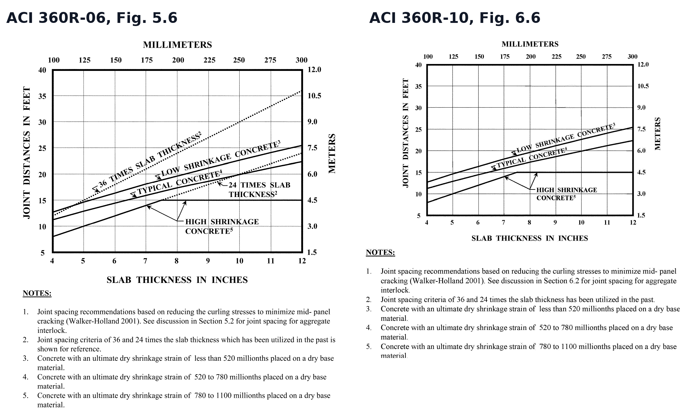
Suggested fix: either restore the lines with a statement of how they relate to the recommended spacings, or delete Note 2.
Discussion
A designer who follows ACI 360R-10 completely arrives at a thickness from an interior-load chart that assumes the slab never curls and every joint transfers load perfectly, a factor of safety chosen from a range without a means to adjust it, and a list of considerations the guide raised but did not quantify: curl, loads at joints, joint opening, support stiffness by load type, closely spaced posts, small hard wheels, and the vapor retarder. The design will be the same whether the joints are doweled or not, whether the slab is on a vapor retarder or not, and whether the building is humidity-controlled or not.
The guide deserves credit for raising each of these issues; most are real and important, and some, such as the curling discussion in Chapter 14, are thorough. The difficulty is that raising an issue is half of guidance. A warning without a method leaves the designer on record as having been told of a risk with no means to address it, which is the least defensible position for a young engineer and of little help to the owner. It also leaves contractors exposed, since joint and curl problems typically produce the first call to the builder.
The findings fall into two kinds. Some are internal conflicts that can be fixed by choosing one statement (Findings 1, 6, 11, 13, 15, 16, 19) or by editing (Findings 20 to 25). The rest are gaps, and two remedies are available for each. Where a simple method exists (a joint factor, a curl-stress estimate, a joint-opening estimate, static and dynamic k-values), the guide can present it with a worked example. Where only analysis can address the issue (curl with loss of support, load transfer that depends on joint opening, multiple loads on a panel), the guide can say so plainly and provide input guidance for the finite element analysis it already describes as appropriate for jointed slabs.
Recommendations
- Adopt a completeness criterion for each design decision: state the issue, provide a method with an example, or state that the method does not cover it and identify one that does.
- Bring the PCA method to the 2008 edition, including the joint factor, free-edge and edge post charts, and effective contact area, and work the Appendix 1 examples with and without load transfer (Findings 2, 3, 17, 18).
- Remove the WRI method, and either remove the COE method or limit it to joints with effective load transfer, with a current source (Findings 6, 7).
- State in Chapter 7 what each method covers and omits, and reconcile Sections 4.4.7, 5.8, 7.2, and 14.13 (Findings 1, 11).
- Use one fatigue basis, define the stress ratio on load and curl analyzed together where they coincide, compared with a slab capacity converted from the beam strength, and state the allowable repetitions in every example (Finding 16).
- Provide a method for estimating joint opening, align the dowel trigger with the dowel table, and report aggregate interlock results as LTE (Findings 9, 10, 12).
- Define static and dynamic k-values, give a calibrated estimation method, state which loads use which, and separate settlement from slab design (Findings 14, 15).
- Give minimum modeling requirements for finite element analysis, including load transfer by joint type and curl (Findings 5, 8).
- Correct the editorial errors before any reprint (Findings 20 to 25).
Conclusions
Measured against the goal that a new engineer should be able to design a slab from it, ACI 360R-10 raises the right issues and resolves few of them. Followed in order for an ordinary spec warehouse, it yields a thickness that ignores the joint detail, and a set of instructions the designer cannot carry out: 25 findings, about a third of them conflicts between the guide's own statements. Every addition recommended here uses information the guide already contains or methods already published. The guide does not need to say more; it needs to finish what it says.
References
1.ACI Committee 360. Guide to Design of Slabs-on-Ground. ACI 360R-10. American Concrete Institute, Farmington Hills, Mich., 2010.
2.Rodden, R. Reinforcement Continued Through Sawcut Contraction Joints in Slabs-on-Ground: Limits of a Section-Level Shrinkage Solution. Technical Paper TSD-09TP. The Slab Designer, LLC, 2026.
3.Rodden, R. Light Reinforcement Through Sawcut Joints: Tolerances and the JRCP Record. Technical Paper TSD-10TP. The Slab Designer, LLC, 2026.
4.Parkes, N., and R. Rodden. Full Support, Interior Loads, and the Missing Joint Factor: The Thickness Methods of ACI 360R-10 and Their PCA Lineage. Technical Paper TSD-05TP. The Slab Designer, LLC, 2026.
5.Rodden, R. Joint Spacing, Curling, and the Factor of Safety in ACI 360R-10: Two Assumptions the Guide's Own Data Do Not Support. Technical Paper TSD-07TP. The Slab Designer, LLC, 2026.
6.Farny, J. A., and S. M. Tarr. Concrete Floors on Ground, 4th ed. EB075. Portland Cement Association, Skokie, Ill., 2008.
7.Department of Defense. Concrete Floor Slabs on Grade Subjected to Heavy Loads. UFC 3-320-06A. Unified Facilities Criteria, Washington, D.C., 2005.
8.Colley, B. E., and H. A. Humphrey. Aggregate Interlock at Joints in Concrete Pavements. Highway Research Record 189, Highway Research Board, Washington, D.C., 1967.
9.Rodden, R. The Modulus of Subgrade Reaction for Slabs-on-Ground: Static Stiffness, Dynamic Stiffness, and Long-Term Settlement. Technical Paper TSD-06TP. The Slab Designer, LLC, 2026.
10.American Association of State Highway and Transportation Officials. Mechanistic-Empirical Pavement Design Guide: A Manual of Practice, 2nd ed. AASHTO, Washington, D.C., 2015.
11.Covarrubias, J. P., R. Rodden, L. Khazanovich, J. Roesler, and N. Parkes. Mechanistic-Empirical Design of Concrete Slabs-on-Ground. Concrete International, American Concrete Institute, July 2026.
12.ACI Committee 360. Design of Slabs on Grade. ACI 360R-92 (Reapproved 1997). American Concrete Institute, Detroit, Mich., 1992.
13.ACI Committee 360. Design of Slabs-on-Ground. ACI 360R-06. American Concrete Institute, Farmington Hills, Mich., 2006.
Related in This Series
- Article on this topic: The Design Guide a New Engineer Can't Design From
A new engineer follows ACI 360R-10 step by step and finds the places it raises an issue and stops.
- The Thickness Methods of ACI 360R-10 and Their PCA Lineage
Traces how PCA added a joint factor in 2001 and 2008 that ACI 360R-10's thickness procedure still omits.
- PCA's Airport Pavement Method on Industrial Floors
Validates a rebuild of PCA's 1973 airport method and explains why its flexible inputs do not make it an industrial floor design basis.
- From Westergaard and Meyerhof to Mechanistic-Empirical Design
Summarizes the 2026 Concrete International and Concrete articles that set out why the Westergaard and Meyerhof methods fall short for modern floors and how the SLABS framework addresses it.
- Slab Thickness as an Outcome, Not an Input
Shows how load transfer, curl, support stiffness, and surface demands, not thickness alone, govern slab performance.
Revision history
- November 4, 2026: Added Finding 25, the Fig. 6.6 note left behind when its lines were removed.
- November 2, 2026: Added links to later pieces in the series.
- October 30, 2026: Gave the PCA 2008 example in inches and millimeters; expanded Findings 8 and 12; added a table of constants (Table 2); added metric units and links to companion papers.
- October 23, 2026: First published on slabs.design/knowledge.
To cite this paper, use the citation printed in the PDF. It includes the revision date, so readers can match your citation to the text you read.