Technical Paper|TSD-03TP
Slab Thickness as an Outcome, Not an Input: Load Transfer, Curling, Support, and Surface Demands in Slab-on-Ground Design
Robert Rodden (The Slab Designer, LLC); Juan Pablo Covarrubias (TCPavements-FORTA)
The Slab Designer, LLC | Published October 22, 2026 | Revised November 4, 2026
Abstract
Slab thickness is the most visible design parameter of an industrial floor and the one owners, real estate agents, tenants, and reviewers most often use to judge it. ACI 360R-10, by contrast, discusses joints nearly three times as often as thickness, and shrinkage about one and a half times as often. The performance-based design methods adopted for highway pavements rank thickness as just one of many sensitive inputs. This paper examines what thickness does and does not control in a slab-on-ground. A recent mechanistic-empirical comparison of seven slab systems for the same warehouse produced required thicknesses from 10 in. (250 mm) to 5 in. (130 mm); the 3 in. (75 mm) difference between an undoweled and a doweled slab came from load transfer alone, and the thinnest slab was the one that reduced curl and joints. Closed-form Westergaard-Bradbury analysis at the joint spacings of ACI 360R-10 Fig. 6.6 shows curling stress roughly doubling from a 5 in. (130 mm) to a 10 in. (250 mm) slab for the same gradient per inch. The PCA aggregate interlock tests cited by ACI 360R-10 show no meaningful benefit from 2 additional inches of concrete once joints open and loads repeat. Under differential settlement, a thicker slab opens joints and cracks wider at the surface and adds 12.5 psf (0.60 kPa) of sustained load per inch. Highway design experience, including one author's 2014 comparison of U.S. design methods, shows that stiffer support can increase required thickness when curling is modeled. The paper recommends that thickness be reported as the outcome of explicit decisions about load transfer, curl, support, and surface demands, and that comparisons between systems be made at equal performance rather than equal thickness.
Keywords: Slab thickness, load transfer efficiency, curling, joint spacing, aggregate interlock, settlement, Pavement ME, slab systems
Introduction
Ask an owner what they know about their warehouse floor and the answer is usually a single number. Thickness appears on every drawing, it can be checked with a core, and it reads intuitively as strength: 6 in. (150 mm) sounds light and 10 in. (250 mm) sounds serious. It is also the quantity that thickness design methods are named for.
The design guidance treats it differently. A word count of ACI 360R-10 (1) finds "joint" and its variants 487 times, the fourth most frequent term after slab, concrete, and load; "shrinkage" 268 times; "thickness" 174 times; and "curl" 121 times. The guide's authors understood that slab performance is governed by the system: joints, shrinkage, curl, support, and load transfer, with thickness one variable among them. The difficulty is that the thickness methods the guide presents compute a thickness from interior load stress alone, so the variables the guide discusses most are the ones least represented in the number it produces.
This paper examines thickness as an outcome of other design decisions rather than an independent measure of quality. It draws on a recent seven-system design comparison (2), closed-form curling analysis using the guide's own inputs, the aggregate interlock data the guide cites (3), simple mechanics of settlement, and the highway experience with mechanistic-empirical design (4, 5).
One Building, Seven Thicknesses
Covarrubias, Parkes, and Rodden (2) designed one 172,800 sq ft (16,050 m²) warehouse seven ways using a mechanistic-empirical framework built on ISLAB2000 finite element analysis, with curl represented by an equivalent built-in temperature difference and load transfer modeled at every joint. Loads (9,600 lb rack posts on 6 in. base plates and a reach truck with small, hard wheels), subgrade (dynamic k of 150 psi/in. [41 MPa/m], static k of 75 psi/in. [20 MPa/m]), and concrete strength were the same for every system. Table 1 summarizes the systems for which thickness was reported.
Table 1. Selected Results From the Seven-System Comparison (2)
| Type | System | Sawcut joint load transfer efficiency | Joint spacing | Required thickness |
|---|---|---|---|---|
| 1 | Unreinforced, undoweled sawcuts | Below 4% (joints open about 0.13 in.) | ACI 360R-10 Fig. 6.6 | 10 in. |
| 2 | Plate dowels in all joints | 90% | ACI 360R-10 Fig. 6.6 | 7 in. |
| 3 | 0.1% steel through sawcuts | 37% | ACI 360R-10 Fig. 6.6 | 9.5 in. (8) |
| 4 to 6 | Extended joints with fibers and SRA, steel fibers, or shrinkage-compensating concrete | Varies | 60 to 120 ft | Converged toward the minimum |
| 7 | Shrinkage-compensating concrete with macrosynthetic fibers | Not governing | 120 ft | 5 in. |
Note: Type 3 thickness from the companion spec-building analysis of the same facility (8).
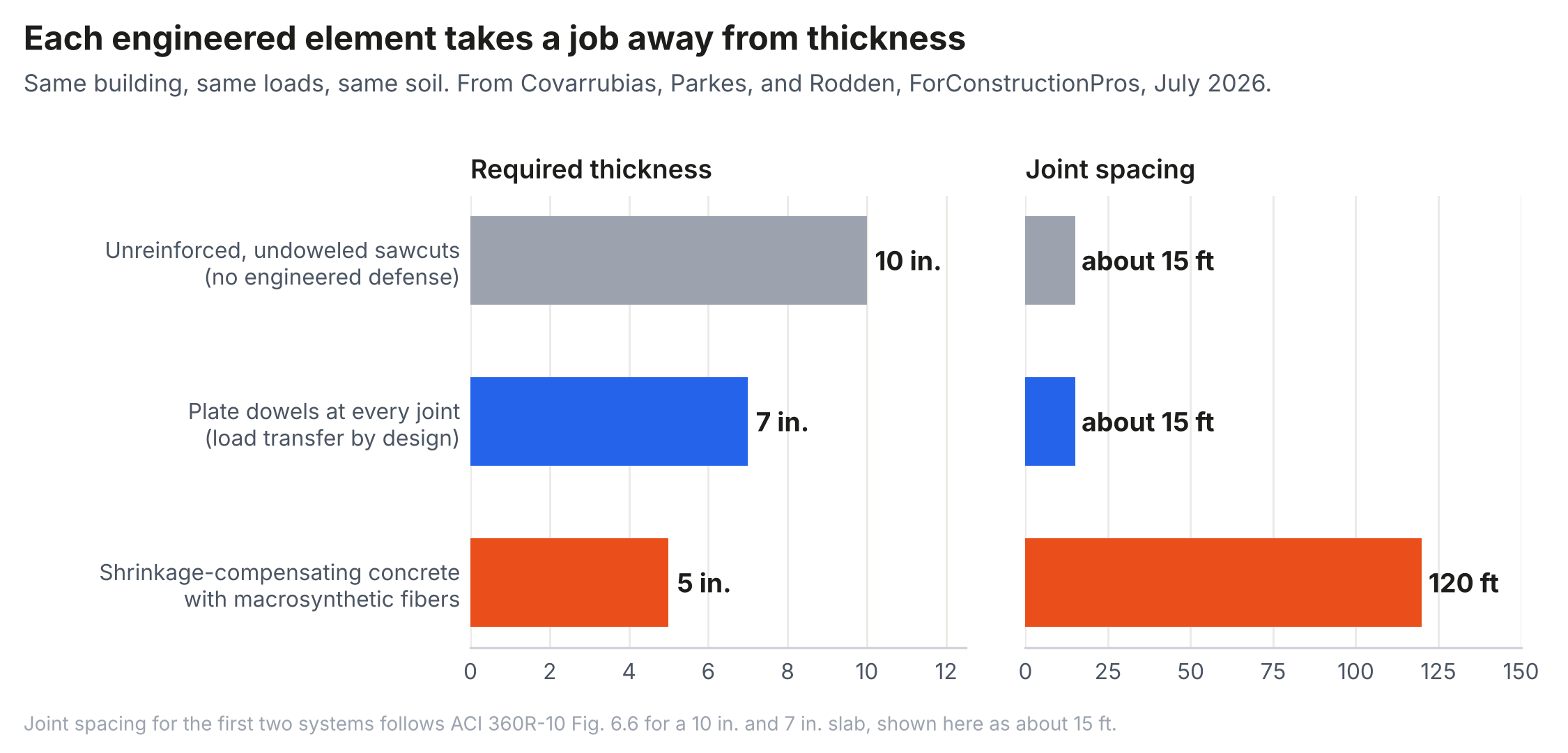
Two results stand out. Types 1 and 2 share joint spacing, concrete, and curl; the 3 in. (75 mm) difference between them is load transfer alone. Load transfer efficiency (LTE) is the ratio of the unloaded-side deflection to the loaded-side deflection at a joint. At 90%, the two sides deflect nearly together and the adjacent panel carries a little under half of a load at the joint (roughly 45%), with the loaded panel carrying the rest; a perfect joint would split the load evenly. At 4%, the loaded panel carries essentially all of it as a free edge. The thickest slab is therefore the one with no engineered load transfer, not the most robust one.
The second result is that the thinnest slab, Type 7 at 5 in. (130 mm), also had the fewest joints. Systems that reduced or offset shrinkage and curl allowed joint spacing of 60 to 120 ft (18 to 37 m) and had 78% to 91% fewer joints than a traditionally jointed slab (2). Joints are where curl, loss of support, spalling, and maintenance concentrate, so the reduction is a performance gain in addition to the reduced section.
Thickness and Curling Stress
Indoor slabs curl upward as the top dries and shrinks more than the bottom. The slab's self-weight resists the curl, and that resistance produces the curling stress. A thicker slab is both heavier and stiffer, and for the same gradient per inch of thickness it develops a larger stress. The Westergaard-Bradbury solution (6, 7), cited by ACI 360R-10 Section 14.13, gives the interior stress in a square panel of side L as
where Δt is the equivalent gradient per inch, h the thickness, and C a coefficient that rises with L/ℓ toward about 1.0, with ℓ the radius of relative stiffness. Table 2 applies Equation 1 at the typical-concrete joint spacing of ACI 360R-10 Fig. 6.6, with E = 4,000,000 psi (27.6 GPa), α = 5.5 microstrain per °F (Section 14.2), μ = 0.15, and the guide's recommended gradients for enclosed slabs (Section 14.13).
Table 2. Interior Curling Stress, psi, at ACI 360R-10 Fig. 6.6 Spacing
| Thickness, in. | Fig. 6.6 spacing, ft | k = 100, 3°F/in. | k = 100, 5°F/in. | k = 150, 3°F/in. | k = 150, 5°F/in. |
|---|---|---|---|---|---|
| 5 | 12.7 | 176 | 294 | 192 | 320 |
| 6 | 14.1 | 204 | 340 | 225 | 375 |
| 7 | 15.5 | 232 | 387 | 258 | 430 |
| 8 | 16.9 | 260 | 434 | 291 | 485 |
| 9 | 18.2 | 290 | 483 | 325 | 541 |
| 10 | 19.6 | 319 | 532 | 359 | 598 |
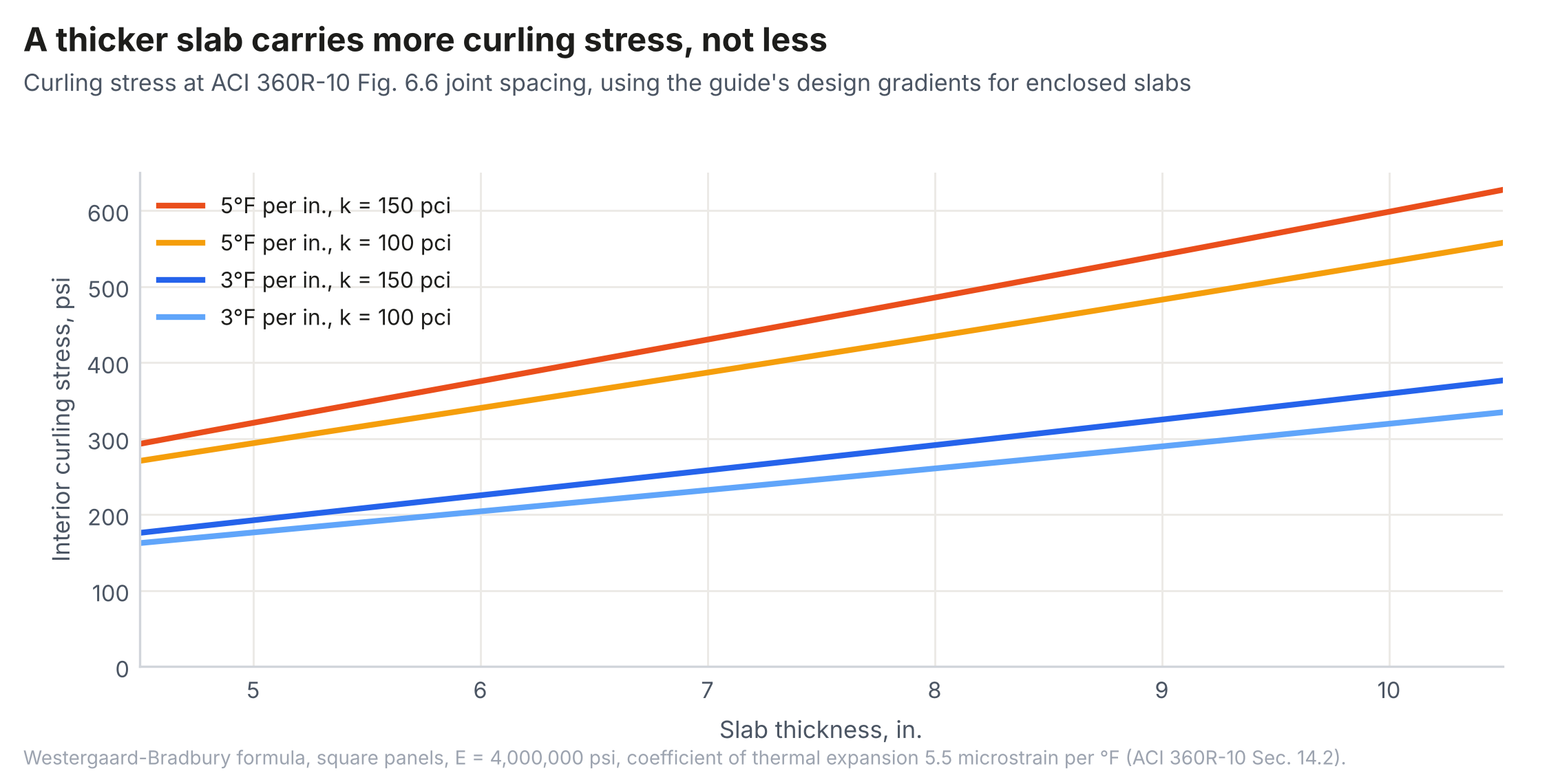
At the same gradient per inch, the 10 in. (250 mm) slab carries roughly 1.8 times the curling stress of the 5 in. (130 mm) slab. Part of the increase comes from the longer joint spacing Fig. 6.6 assigns to thicker slabs, but even at a fixed 15 ft (4.6 m) spacing a 10 in. (250 mm) slab is not meaningfully better off than a 5 in. (130 mm) slab (about 319 compared with 333 psi at 5°F/in. on k = 100). Drying gradients in real slabs are concentrated near the top surface, so the linear-gradient assumption likely overstates the difference; the direction does not change. Thickening does not buy down curling stress. Lower shrinkage, better curing, shorter joint spacing, or a system that offsets shrinkage does.
Thickness and Load Transfer at Joints
ACI 360R-10 bases its aggregate interlock guidance on PCA laboratory tests of 7 and 9 in. (180 and 230 mm) slabs (3). The guide quotes joint effectiveness falling to 60% at openings of 0.025 in. (0.64 mm) for the 7 in. (180 mm) slab and 0.035 in. (0.89 mm) for the 9 in. (230 mm) slab. Joint effectiveness E is not LTE; the two are related by LTE = E/(2 - E), so 60% joint effectiveness is about 43% LTE (8, 9). Re-plotted as LTE against opening, with load repetitions as the parameter, the same data show LTE falling below 90% at an opening of only about 0.015 in. (0.38 mm) once repetitions accumulate, for both slabs. The 2 in. (50 mm) of additional concrete moved the 60% threshold by 0.010 in. (0.25 mm) of opening, a margin that ordinary shrinkage consumes many times over: 400 microstrain over 15 ft (4.6 m) is 15 ft × 12 in./ft × 0.000400 = 0.072 in. (1.8 mm). Thickness does not substitute for load transfer at a joint that opens.
Thickness and Differential Settlement
Thickness is also offered as a remedy for settlement. Two mechanical points argue against it. First, concrete adds sustained load: each inch adds 12.5 psf (0.60 kPa), or 25 psf (1.2 kPa) for 2 in. (50 mm), applied over the entire floor for its life (150 pcf × 1/12 ft). Second, for the same differential settlement between joints, a thicker slab opens wider at the surface. If a panel rotates about its bottom edge at a joint, the surface opening is approximately the thickness times the rotation. For 1 in. (25 mm) of differential settlement across a 15 ft (4.6 m) panel, the rotation is 1/180, and the surface opening is about 0.028 in. (0.71 mm) for a 5 in. (130 mm) slab, 0.039 in. (0.99 mm) for 7 in. (180 mm), and 0.056 in. (1.4 mm) for 10 in. (250 mm). Each 2 in. (50 mm) of thickness adds about 0.011 in. (0.28 mm) of opening, roughly the full 0.010 in. (0.25 mm) joint stability limit ACI 360R-10 sets for small, hard wheels. Settlement is a support problem, and the companion paper on the modulus of subgrade reaction (10) addresses who should own it.
Thickness and Support Stiffness
All three thickness methods in ACI 360R-10 permit a thinner slab when the modulus of subgrade reaction is higher, and the guide calls this an "anomaly" in Section 14.13 because a stiffer support increases curling stress. The highway record confirms it. In a 2014 comparison of U.S. pavement design methods (5), Rodden, Voigt, and Wathne varied the support k-value from 85 to 500 psi/in. (23 to 140 MPa/m). The change reduced required JPCP thickness by about 2 in. (50 mm) in StreetPave and 1 in. (25 mm) in AASHTO 93, both of which ignore curling, by 0.5 in. (13 mm) in Pavement ME at Chicago, and increased required thickness by 0.5 in. (13 mm) in Pavement ME at Phoenix, where curling governs. Only a method that models curl can show that more support sometimes requires more concrete. The same study showed that dowels reduce required JPCP thickness substantially across traffic levels, the highway analog of the 10 in. (250 mm) to 7 in. (180 mm) result in Table 1.
The national sensitivity study of the mechanistic-empirical procedure (4) ranked thickness second among inputs affecting predicted JPCP performance, but the top inputs also included concrete strength and stiffness, joint spacing, edge support, and four properties that control curl: surface shortwave absorptivity, thermal conductivity, coefficient of thermal expansion, and unit weight. Thickness is an important input, but it is one of many.
Thickness and Surface Demands
Some distress that is attributed to inadequate thickness is a surface problem. Trailer dolly pads at docks crush and spall the top of the slab; small, hard polyurethane wheels on modern lift trucks produce very high contact pressures over small areas; and joint edges break down under repeated wheel impacts when the two sides of a joint do not deflect together. These demands depend on surface strength, toughness, abrasion and impact resistance, and joint stability. Adding an inch to the whole floor is an expensive and indirect response to a problem that lives in the top inch or at the joint edge.
Discussion
Thickness is the integral of every other design decision. A floor with no load transfer, ordinary shrinkage, closely spaced joints, and stiff support is thick because thickness is the only lever left; it is not, for that reason, the conservative floor. Conversely, a thin floor is not necessarily under-designed if load transfer, curl, and joints have been addressed explicitly. Comparing floors by thickness alone rewards the least engineered option. The comparison that matters is between systems that meet the same performance criteria: cracking, joint stability, and serviceability over the design life.
This is not a new insight in pavement engineering. Highway design moved from thickness charts to methods that predict cracking, faulting, and roughness, and in doing so learned that stiffer support, longer panels, and higher-shrinkage concrete can each require more thickness rather than less. ACI 360R-10 already discusses every one of those effects. What it lacks is a thickness procedure that includes them.
Recommendations
- Report thickness on drawings together with the decisions that produced it: load transfer assumed at each joint type, joint spacing, curl or shrinkage assumptions, support k-values (static and dynamic), and the loads that governed.
- Compare alternative systems at equal performance, not equal thickness. Where a doweled or low-shrinkage system meets the same criteria at less thickness, the thickness reduction is a result of engineering, not a reduction in quality.
- Do not thicken a slab to address settlement, curl, or open joints. Address support, shrinkage, and load transfer directly.
- Treat surface demands (dolly pads, hard wheels, joint edges) with surface and joint measures: concrete strength and toughness at the surface, hardeners where appropriate, joint armoring, and load transfer.
- Future editions of ACI 360 should present thickness as the output of a procedure that includes load transfer, curling, and support, consistent with the guide's own emphasis on joints and shrinkage.
Conclusions
Thickness is the variable everyone sees and the one the guide's methods compute, but it is not the variable that best predicts slab performance. In a seven-system comparison for one warehouse, required thickness ranged from 10 to 5 in. (250 to 130 mm), and the thickest slab was the least engineered. Curling stress at the guide's own joint spacing rises with thickness; 2 in. (50 mm) of extra concrete did not preserve aggregate interlock in the tests the guide cites; a thicker slab opens wider under the same differential settlement; and the highway record shows that more support can require more concrete when curl is modeled. Thickness should be reported as an outcome of explicit decisions about load transfer, curl, support, and surface demands.
References
1.ACI Committee 360. Guide to Design of Slabs-on-Ground. ACI 360R-10. American Concrete Institute, Farmington Hills, Mich., 2010.
2.Covarrubias, J. P., N. Parkes, and R. Rodden. Concrete Slab-On-Ground Thickness Requirements From Modern Design. ForConstructionPros, July 2026.
3.Colley, B. E., and H. A. Humphrey. Aggregate Interlock at Joints in Concrete Pavements. Highway Research Record 189, Highway Research Board, Washington, D.C., 1967.
4.Schwartz, C. W., R. Li, S. H. Kim, H. Ceylan, and K. Gopalakrishnan. Sensitivity Evaluation of MEPDG Performance Prediction. NCHRP Project 1-47 Final Report. National Cooperative Highway Research Program, 2011.
5.Rodden, R., G. Voigt, and L. Wathne. Comparison of Roadway Jointed Plain Concrete Pavement (JPCP) Thickness Design Methods Common in the United States. Proceedings, 12th International Symposium on Concrete Roads, 2014.
6.Westergaard, H. M. Analysis of Stresses in Concrete Roads Caused by Variations of Temperature. Public Roads, Vol. 8, No. 3, 1927, pp. 54-60.
7.Bradbury, R. D. Reinforced Concrete Pavements. Wire Reinforcement Institute, Washington, D.C., 1938.
8.Parkes, N., R. Rodden, and J. P. Covarrubias. Joint Load Transfer and Slab Thickness for Speculative Warehouse Floors: Undoweled, Doweled, and Lightly Reinforced Joints. Technical Paper TSD-08TP. The Slab Designer, LLC, 2026.
9.Rodden, R. Reinforcement Continued Through Sawcut Contraction Joints in Slabs-on-Ground: Limits of a Section-Level Shrinkage Solution. Technical Paper TSD-09TP. The Slab Designer, LLC, 2026.
10.Rodden, R. The Modulus of Subgrade Reaction for Slabs-on-Ground: Static Stiffness, Dynamic Stiffness, and Long-Term Settlement. Technical Paper TSD-06TP. The Slab Designer, LLC, 2026.
Related in This Series
- Article on this topic: Thickness Ain't Nothin' but a Number
Why the thickest slab is often the least engineered one, and what the roads learned when they measured it.
- Industrial Slab Systems as Positions in One Design Space
Proposes organizing slab guidance around physical design levers so new systems are evaluated as engineering, not products.
- Raised but Not Resolved: An Audit of ACI 360R-10
Audits eight design decisions in ACI 360R-10 for whether each issue raised is carried through to a design method.
- The Evolution of Concrete Pavement Design and Its Lessons for Slabs-on-Ground
A century of pavement design organized around the problems that drove it, set alongside the development of slabs-on-ground.
- The Thickness Methods of ACI 360R-10 and Their PCA Lineage
Traces how PCA added a joint factor in 2001 and 2008 that ACI 360R-10's thickness procedure still omits.
Revision history
- November 4, 2026: Added metric units to k-values.
- October 30, 2026: Added links to later pieces in the series.
- October 29, 2026: Completed references; added metric units and links to other pieces in the series.
- October 22, 2026: First published on slabs.design/knowledge.
To cite this paper, use the citation printed in the PDF. It includes the revision date, so readers can match your citation to the text you read.