Technical Paper|TSD-02TP
Industrial Slab Systems as Positions in One Design Space: A Framework for Organizing Slab-on-Ground Guidance Around Fundamentals
Robert Rodden (The Slab Designer, LLC); Juan Pablo Covarrubias (TCPavements-FORTA)
The Slab Designer, LLC | Published October 21, 2026 | Revised November 4, 2026
Abstract
Industrial slabs-on-ground have no material competitor indoors, and unlike highway pavements they have never had an organized industry program tracking market share, funding research, and collecting performance data. Innovation in the niche has come almost entirely from private engineers, contractors, and manufacturers: laser screeds and large block placements, plate dowels, armored and profiled joints, fibers, shrinkage-reducing admixtures, shrinkage-compensating concrete, post-tensioning, and engineer-built finite element design methods. Because these developments usually arrive attached to a product or firm, consensus guidance has tended to set them aside as proprietary, while the design methods it presents remain rooted in Westergaard's 1920s idealization. This paper argues that the slab systems in use are not competing products but different positions in one design space, defined by enough physical levers to differentiate one slab system from the next, including support stiffness and uniformity, base restraint, shrinkage and curl, thermal movement, joint spacing, load transfer, joint protection, material toughness and slab capacity, and loading. A seven-system comparison for one warehouse illustrates the point; required thickness ranged from 10 in. (250 mm) to 5 in. (130 mm) and joint count fell by 78% to 91% as systems pulled harder on the shrinkage, curl, and joint levers, with nothing proprietary about the physics. The paper proposes that future guidance be organized around these levers, with each slab system described by the levers it uses and the analysis inputs it requires, so that the question for any system becomes how it changes the slab and by how much.
Keywords: slab-on-ground, innovation, design guidance, slab systems, joints, shrinkage, curl, load transfer, ACI 360
Introduction
Concrete pavement began outdoors, as a rut-resistant surface for horse-drawn traffic, and moved indoors once it had proven itself. Factory floors of the 19th century were wood block, brick, or stone set by hand; concrete displaced them and has held the industrial floor market essentially without competition since. Outdoors, concrete competes with asphalt for roads, streets, and airfields, and the concrete pavement industry organized around that competition: trade associations track paving quantities and market share as key performance indicators and fund research, guidance, and promotion to move them. Indoors there is no competitor to track. The Portland Cement Association once supported the floor market through Concrete Floors on Ground (1), and the American Concrete Pavement Association considered industrial floors more than once but kept its focus on roads and airfields. ACI Committees 302 and 360, on floor construction and slab-on-ground design, are the principal venues where the niche meets.
This paper examines what that structure has produced, why consensus guidance has had difficulty absorbing it, and how guidance could be organized so that it can.
Innovation Without a Program
Industrial floors arguably changed faster than any other part of the concrete industry over the last four decades, and almost all of the change came from the private market.
Loads changed first. Lift trucks moved from pneumatic tires to small, hard polyurethane wheels with very high contact pressures. Storage moved from selective pallet racks to very narrow aisle systems, automated storage and retrieval systems, and most recently data centers. The floor became a piece of operating equipment that sets how high and how fast a facility can work.
Construction followed. Laser-guided screeds made large block placements economical and reduced construction joints. Larger placements exposed the restraint that round dowels impose at joint intersections, and manufacturers responded with plate dowels, including tapered geometries, that transfer load while permitting movement in both horizontal directions. As construction joints moved farther apart and became the joints that open most, they were first armored with straight steel and then given profiled edges so wheels cross gradually. Shake-on hardeners and shrinkage-compensating concrete were adopted where abrasion governs, and dedicated abrasion tests followed. Steel and macrosynthetic fibers, shrinkage-reducing admixtures, shrinkage-compensating concrete, and post-tensioning all enabled floors with far fewer joints than the traditional rules allowed.
Design followed as well. In few other parts of the concrete flatwork industry have practicing engineers built their own finite element analyses and design methods because the published guidance did not answer their questions. Structural engineers may build their own models for unusual structures, and specialized military applications, such as slabs loaded by maneuvering tanks, call for their own materials testing and analysis. But consultants designing highways, streets, and airfields use published methods and software; they do not write their own.
The market moved ahead of the guidance in measurable ways. ACI 360R-10 (2) recommends plate dowels at 18 in. (460 mm) on center. By 2017, the largest plate dowel manufacturer reported that only 44% of the baskets it sold over three years were spaced at 18 in. (460 mm), with most of the remainder at wider spacings, reflecting research and market changes since the guide's fixed 18 in. (460 mm) recommendation (3, 4).
Why Guidance Lags
Consensus guidance moves slowly by design. Garber (5) describes standards as written for ordinary circumstances, conservative because "it normally takes years for a standard-writing committee to adopt a new idea," and unable to replace the designer's own analysis, and he quotes the British Standards Institution: "Compliance with the British Standard does not of itself confer immunity from legal obligations." ACI Committee 360 has published three editions of its guide: 360R-92 (57 pages, a committee of 11), 360R-06 (74 pages, 29 members), and 360R-10 (72 pages, 29 members), and it is now 16 years since the last edition, with a committee of 33. The 2006 edition was introduced as bringing slab design "into the 21st Century" (6); its thickness methods were the Westergaard-based procedures of the 1920s through the 1970s, alongside yield-line methods such as TR34 that make comparable idealizations.
A second obstacle is structural. When innovation comes entirely from the private market, it tends to arrive attached to a product or a patent. Within ACI Committee 360, that has hardened into a working assumption that anything deemed proprietary cannot be mentioned, and approaches proven in the field are set aside on that basis while the guide remains where it was. The assumption is rarely questioned, and it reads ACI's procedures more broadly than they are written. The ACI Technical Committee Manual (10) is more specific, and it separates two ideas the committee conversation tends to merge: patented technology and proprietary technology.
The word "proprietary" appears in the manual in two places, and neither governs guides. Section 4.2.8, in the chapter on developing standards (codes and specifications), states that "ACI technical committee standards cannot and do not endorse or promote patented products or proprietary technology of any kind" and that standards "shall not refer directly to a particular patent or proprietary technology by use of trademarks or trade names." Even for standards, the manual allows that they "may allow patented technology as a possible solution"; what they "shall not" do is mandate it. Section 12.1, on convention sessions, states that presentations "that promote the use of proprietary products without sufficient, objective, supporting data are generally not acceptable." What applies to every committee document concerns patents, not proprietary methods, and it is procedural: during balloting, "the committee must be informed if the document refers to the use of patented technology" (Section 3.2.7), and a document that includes patented items carries the patent disclaimer of Section 14.2.7. Even code commentaries, which are written in nonmandatory language, "may refer to patented items that can be used to meet the intent of a specific provision" (Section 4.1.1.1).
Read together, these provisions expect patented technology to appear in ACI documents and set out how to handle it, restrict endorsement and trade names in mandatory standards, and contain nothing that bars a guide from describing a proprietary method. Proprietary is also not the same as patented. Many design methods, including most engineering software, are proprietary only in the sense that the owner does not publish the full method or code; they hold no patents and raise no patent question. The test the manual applies to convention presentations is a reasonable one for guides as well: whether a method is supported by sufficient, objective data, not whether someone owns it.
A sister committee has already described proprietary tools in a guide. ACI Committee 330's guide for industrial and trucking facility paving (11) includes a section titled "Proprietary design software" (Section B.1) that describes four programs by name, ACPA PavementDesigner.org, AASHTOWare Pavement ME Design, TCPavements OptiPave, and ACPA AIRPave, with what each one does. Naming proprietary methods in a guide is not only allowed; it has already been done in an industrial concrete flatwork guide, because designers need to know the tools exist. Guidance can describe what a patented or proprietary approach does, and include the alternatives that provide the same benefit, without endorsing any of them. An engineering question should not be decided by who first commercialized the answer.
One Design Space
The physical quantities every slab-on-ground design balances include variables such as:
- the stiffness and uniformity of support;
- restraint from the base, through friction and keying;
- drying shrinkage and the curl it produces;
- thermal movement;
- joint spacing;
- load transfer across joints;
- protection of joint edges;
- material toughness and slab capacity; and
- the loads themselves, described realistically in magnitude, contact, position, and repetition.
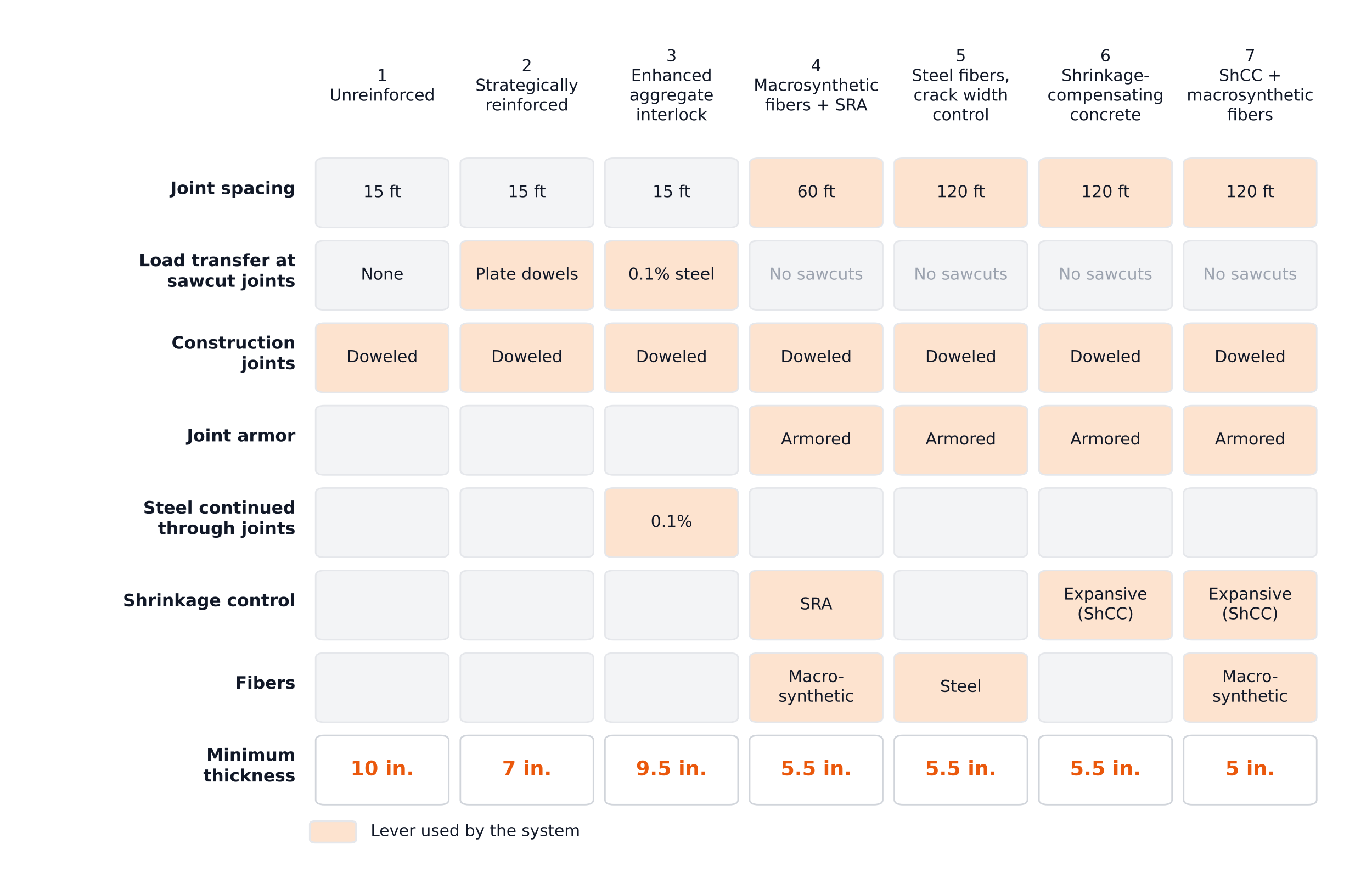
The list is not exhaustive. It needs only enough levers to differentiate one slab system from the next. Each slab system is a different combination of them (Figure 1). An unreinforced slab with sawcut joints and no load transfer pulls almost none of them deliberately and relies on thickness. A doweled slab pulls load transfer. A slab with 0.1% steel through the sawcuts pulls restraint and, to a limited degree, load transfer. Fiber-reinforced and shrinkage-reduced slabs pull material toughness and shrinkage, which allows longer joint spacing, and the fewer joints that remain are doweled and armored; shrinkage-compensated slabs offset shrinkage; post-tensioned slabs apply precompression to eliminate most joints. None of these is a different physics. Each is a different position in the same space.
A Worked Comparison
Figure 1 summarizes the systems in principle. This section documents the comparison behind it: the same levers, pulled with real engineering inputs, carried through the calculations, and reported as outputs.
Covarrubias, Parkes, and Rodden (7) designed one 172,800 sq ft (16,050 m²) warehouse seven ways, with full design examples published separately (12). Every system was analyzed with the same mechanistic-empirical framework, based on ISLAB2000 finite element analysis, with curl represented as an equivalent built-in temperature difference (EBITD) and load transfer modeled at each joint. The building, location, loads, and support were held constant (Table 1). What changed from one system to the next were the levers each system pulls: joint spacing, the detail at the joints, shrinkage, curl, and the concrete (Table 2).
Table 1. Design Inputs Held Constant (7, 12)
| Item | Value |
|---|---|
| Facility | 172,800 sq ft (16,050 m²), 720 x 240 ft (219 x 73 m), 60 x 60 ft (18 x 18 m) column bays |
| Support | Subgrade resilient modulus 5,800 psi (40 MPa): dynamic k 150 psi/in. (41 MPa/m), static k 75 psi/in. (20 MPa/m) |
| Base friction | 0.50, on a 15 mil vapor retarder |
| Thermal | Setting temperature 100°F (38°C); mean annual facility temperature 70°F (21°C); coefficient of thermal expansion 4.5 microstrain/°F |
| Racks | Back to back, 9,600 lb (42.7 kN) post loads on 6 in. (150 mm) base plates; allowable stress ratio 0.80; static k |
| Lift truck | Three-wheel reach truck, small, hard wheels, 3,000 lb (13.3 kN) load; allowable stress ratio 0.45 for unlimited repetitions; dynamic k |
Table 2. The Levers Each System Pulls, and the Result (7, 12)
| Type | System | Joint spacing | Sawcut joints | EBITD | Shrinkage, microstrain | Minimum thickness | Interior joints |
|---|---|---|---|---|---|---|---|
| 1 | Unreinforced | 15 ft (4.6 m) | Undoweled | −25°F | 600 | 10 in. (250 mm) | 22,080 ft (6,730 m) |
| 2 | Strategically reinforced | 15 ft (4.6 m) | Plate dowels | −25°F | 600 | 7 in. (180 mm) | 22,080 ft (6,730 m) |
| 3 | Enhanced aggregate interlock | 15 ft (4.6 m) | 0.1% steel through the sawcut | −25°F | 600 | 9.5 in. (240 mm) | 22,080 ft (6,730 m) |
| 4 | Macrosynthetic fibers and shrinkage-reducing admixture | 60 ft (18 m) | None | −5.5°F | 400 | 5.5 in. (140 mm) | 4,800 ft (1,460 m) |
| 5 | Steel fibers, crack width control | 120 ft (37 m) | None | −18°F | 600 | 5.5 in. (140 mm) | 1,920 ft (585 m) |
| 6 | Shrinkage-compensating concrete | 120 ft (37 m) | None | −5.5°F | 300 | 5.5 in. (140 mm) | 1,920 ft (585 m) |
| 7 | Shrinkage-compensating concrete with macrosynthetic fibers | 120 ft (37 m) | None | −5.5°F | 300 | 5 in. (130 mm) | 1,920 ft (585 m) |
Note: Construction joints are doweled in every type and armored in Types 4 to 7.
The joint detail is a lever with a large effect by itself. In Type 1 the sawcut joints are expected to open about 0.13 in. (3.3 mm), leaving load transfer efficiency (LTE) below 4%. Type 2 uses plate dowels designed for 90% LTE, and Type 3's 0.1% steel provides about 37% LTE (8). Types 1 and 2 share joint spacing, concrete, and curl, so the 3 in. (75 mm) between them is load transfer alone; Type 3 recovers only 0.5 in. (13 mm) of it. The curl lever explains most of the rest. Types 1 to 3 share an EBITD of −25°F; Types 4, 6, and 7 reduce it to −5.5°F through shrinkage-reducing admixture, shrinkage-compensating concrete, and fibers, which allows joint spacing of 60 to 120 ft (18 to 37 m), 78% to 91% fewer joints, and thicknesses of 5 to 5.5 in. (130 to 140 mm).
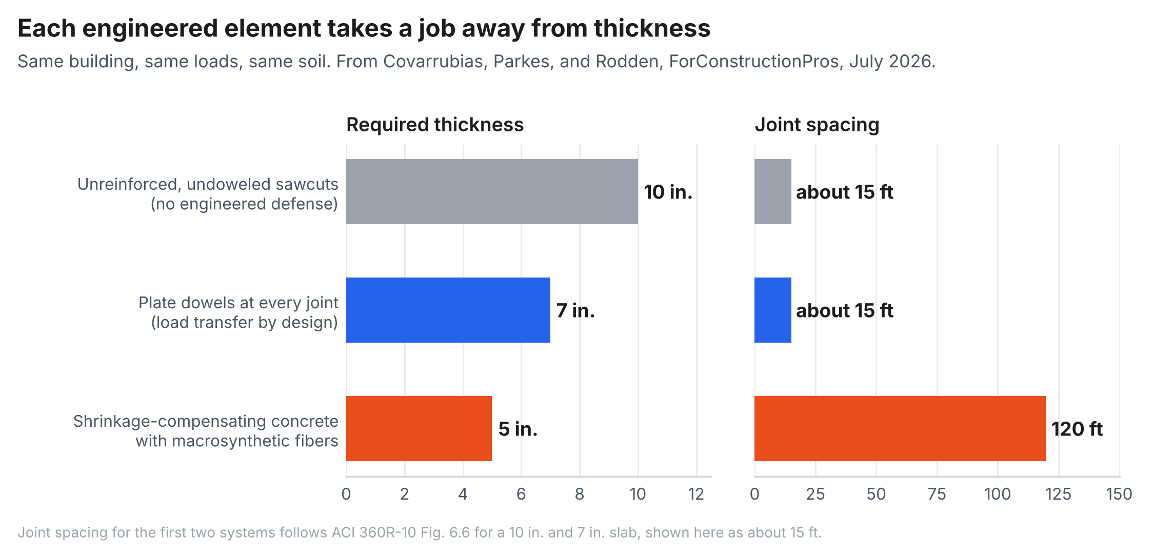
Nothing about the 5 in. (130 mm) design is proprietary. It pulls harder on the shrinkage, curl, and joint spacing levers, and the mechanics respond. The same analysis framework produced every result in the comparison, which is the point: when the levers are inputs to a common analysis, systems can be compared on engineering terms rather than on commercial ones. Thickness alone is a poor guide to the result. The thickest slab, Type 1, has the worst expected serviceability, and Types 4 to 7 converge on nearly the same thickness by different means, so what separates them is joint performance and maintenance.
A Framework for Guidance
Organizing guidance around the levers rather than around systems or products would allow new developments to be evaluated without endorsing anyone. A guide organized this way would contain, for each lever, the governing mechanics, the measurable inputs, the test methods for those inputs, and the range of values supported by data. Table 3 sketches the mapping.
Table 3. Design Levers, Required Inputs, and Systems That Rely on Them
| Lever | Inputs a design needs | Systems that rely on it most |
|---|---|---|
| Support | Static and dynamic k-value, uniformity, settlement criteria | All |
| Base restraint | Friction coefficient of the base or vapor retarder | Long-joint slabs, tied joints, post-tensioned slabs |
| Shrinkage and curl | Drying shrinkage, curl as an effective built-in temperature difference, curing | All; shrinkage-reduced and shrinkage-compensated slabs |
| Joint spacing | Spacing, layout, construction versus sawcut joints | All |
| Load transfer | Load transfer efficiency as a function of joint opening; device stiffness | Doweled slabs, tied joints |
| Joint protection | Armoring, edge profile, filler | Long-joint slabs |
| Thermal movement | Setting and service temperatures, coefficient of thermal expansion | Long-joint slabs, refrigerated and unconditioned buildings |
| Material toughness and slab capacity | Slab flexural capacity, including any fiber contribution; abrasion resistance | All; fiber-reinforced and hardened-surface slabs |
| Loading | Magnitude, contact area and pressure, position relative to joints, repetitions | All |
Under this organization, a slab system is described by the levers it uses and the evidence for the values it assumes, and the design question becomes: how does this choice change the slab, and by how much? That question has an engineering answer regardless of who sells the system. Historical methods such as Westergaard's solutions and yield-line analysis fit within the same framework as special cases that fix several levers at idealized values (full support, no curl, perfect or no load transfer).
The framework also points to the data the niche lacks. Highway design improved as national performance data accumulated. Floors have no comparable program. Measured joint openings, curl from floor profilers, differential deflections at joints, and cracking tied to design details would allow the lever values in Table 3 to be calibrated rather than assumed (9).
Discussion
Industrial floors have had plenty of competition, all of it inside the concrete industry: system against system and method against method, debated in committees that meet twice a year and revise their guides about once a decade. That pace suited a market in which loads, buildings, and tools changed slowly. Automated facilities now move from design to operation in one to two years, and analyses that once took weeks run in seconds. Guidance organized around fundamentals can absorb new systems as they appear, because it evaluates the levers they pull rather than the names they carry.
Recommendations
- Organize future slab-on-ground guidance around physical levers such as support, restraint, shrinkage and curl, thermal movement, joint spacing, load transfer, joint protection, material toughness and slab capacity, and loading.
- Describe each slab system by the levers it uses and the inputs it requires, with the evidence supporting those inputs, rather than by product category.
- Treat Westergaard and yield-line methods as special cases within the framework, with their idealizations stated.
- Provide guidance for mechanistic-empirical analysis that takes the levers as inputs, since the guide already identifies such analysis as appropriate for jointed slabs.
- Establish a mechanism for collecting floor performance data (joint opening, curl, joint stability, cracking) tied to design details.
Conclusions
The industrial floor niche innovated on its own because no industry program existed to do it, and much of what it developed has outrun consensus guidance that remains built on 1920s idealizations and wary of anything with a commercial origin. The slab systems in use are best understood as different positions in one design space, defined by enough physical levers to differentiate one system from the next. A seven-system comparison for one warehouse shows how strongly those levers govern thickness and joint count. Organizing guidance around them would let the industry's best ideas be evaluated as engineering rather than dismissed as proprietary.
References
1.Farny, J. A., and S. M. Tarr. Concrete Floors on Ground, 4th ed. EB075. Portland Cement Association, Skokie, Ill., 2008.
2.ACI Committee 360. Guide to Design of Slabs-on-Ground. ACI 360R-10. American Concrete Institute, Farmington Hills, Mich., 2010.
3.PNA Construction Technologies. Standardized Basket Design Reduces Project Costs. August 2017.
4.Walker, W. W., and J. A. Holland. Performance-Based Dowel Design. Concrete Construction, 2007.
5.Garber, G. Design and Construction of Concrete Floors, 2nd ed. Butterworth-Heinemann, Oxford, 2006.
6.McKinney, A. W. ACI 360R-06 Brings Slabs on Ground Design into the 21st Century. STRUCTURE Magazine, January 2007.
7.Covarrubias, J. P., N. Parkes, and R. Rodden. Concrete Slab-On-Ground Thickness Requirements From Modern Design. ForConstructionPros, July 2026.
8.Parkes, N., R. Rodden, and J. P. Covarrubias. Joint Load Transfer and Slab Thickness for Speculative Warehouse Floors: Undoweled, Doweled, and Lightly Reinforced Joints. Technical Paper TSD-08TP. The Slab Designer, LLC, 2026.
9.Rodden, R. The Evolution of Concrete Pavement Design in the United States and Its Lessons for Slabs-on-Ground. Technical Paper TSD-01TP. The Slab Designer, LLC, 2026.
10.ACI Committee on Technical Committee Procedures. ACI Technical Committee Manual. American Concrete Institute, Farmington Hills, Mich., revised July 2026. Sections 3.2.7, 4.1.1.1, 4.2.8, 12.1, and 14.2.7.
11.ACI Committee 330. Design and Construction of Concrete Site Paving for Industrial and Trucking Facilities. ACI 330.2R-17. American Concrete Institute, Farmington Hills, Mich., 2017. Appendix B, Section B.1.
12.The Slab Designer, LLC. Design Examples: Seven Common Slab-on-Ground Types Evaluated Under Identical Loading and Support Conditions. https://slabs.design/design-examples. Accessed November 2026.
Related in This Series
- Article on this topic: When Concrete Has No Competition
Industrial floors innovated without an industry program behind them. The guidance hasn't kept up.
- The Evolution of Concrete Pavement Design and Its Lessons for Slabs-on-Ground
A century of pavement design organized around the problems that drove it, set alongside the development of slabs-on-ground.
- Slab Thickness as an Outcome, Not an Input
Shows how load transfer, curl, support stiffness, and surface demands, not thickness alone, govern slab performance.
- Raised but Not Resolved: An Audit of ACI 360R-10
Audits eight design decisions in ACI 360R-10 for whether each issue raised is carried through to a design method.
- The Thickness Methods of ACI 360R-10 and Their PCA Lineage
Traces how PCA added a joint factor in 2001 and 2008 that ACI 360R-10's thickness procedure still omits.
Revision history
- November 4, 2026: Corrected the description of ACI's rules on proprietary items; redrew Figure 1; clarified the scope of ACI's restriction on proprietary items; named TCPavements OptiPave; broadened the design levers; expanded the worked comparison with its inputs and results; rewrote the ACI Technical Committee Manual discussion from its full text (Sections 3.2.7, 4.1.1.1, 4.2.8, 12.1, and 14.2.7); replaced post-cracking capacity with slab capacity.
- October 29, 2026: Added links to later pieces in the series.
- October 28, 2026: Reworked the proprietary-methods discussion with the ACI 330.2R-17 example; clarified the flatwork comparison; added metric units and links.
- October 21, 2026: First published on slabs.design/knowledge.
To cite this paper, use the citation printed in the PDF. It includes the revision date, so readers can match your citation to the text you read.